Wiring Setup - Eco Saver Kit
1. Unpack the wires and the PLH3D-6W-XF+ Laser Head.
To check if you have all the needed items, head over to the Included Parts section of this manual.
2. Mount the PLH3D-6W-XF+ Laser Head to your machine.
Most machines will require you to use an additional mount to install your laser head. Mounts are not included in the Eco Kits, but can be purchased separately.
You can also prepare one yourself. To see examples of mounting of the laser head to a specific CNC machine, you can head over to other CNC Machine Laser Upgrade Instructions.
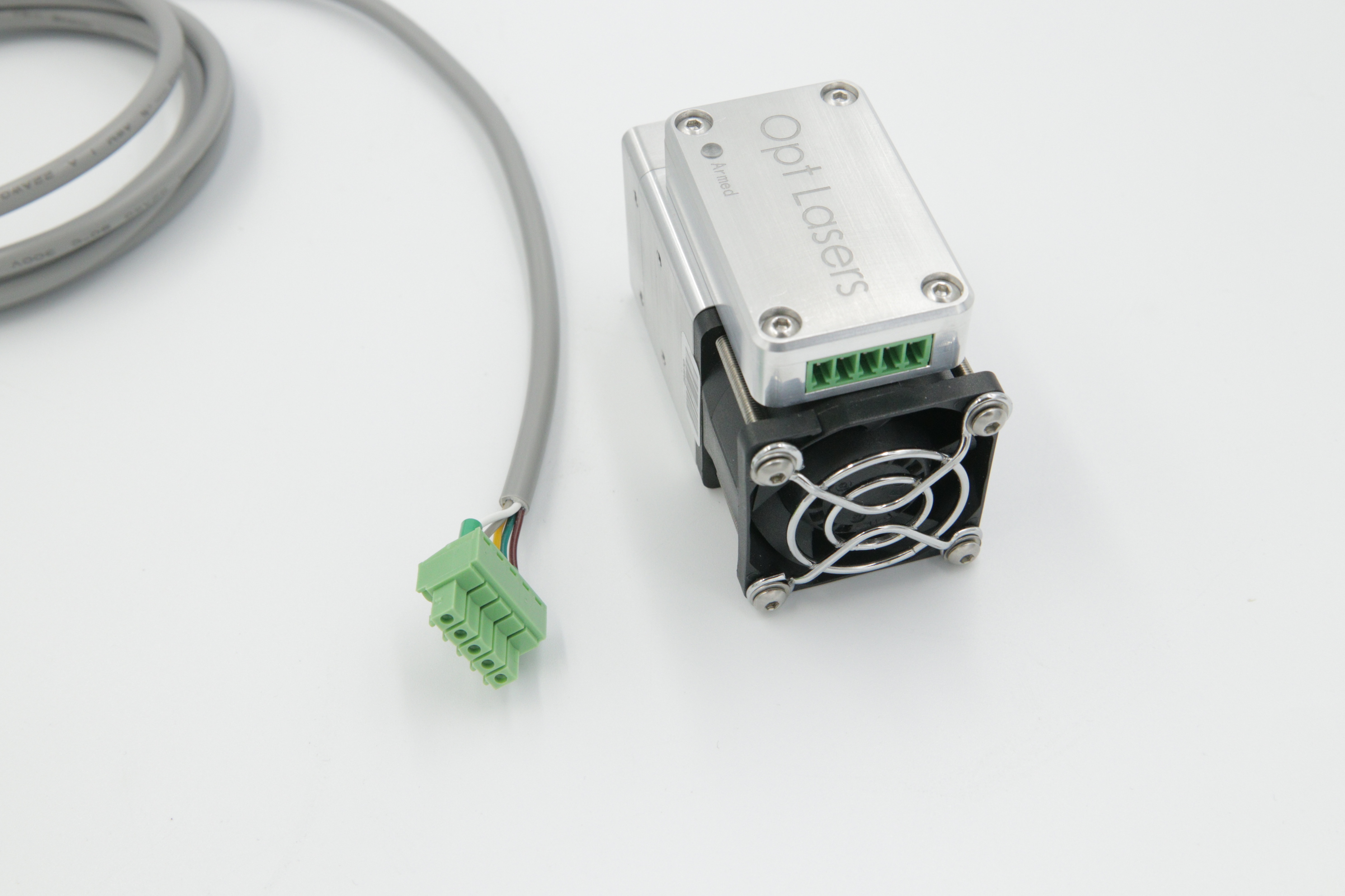
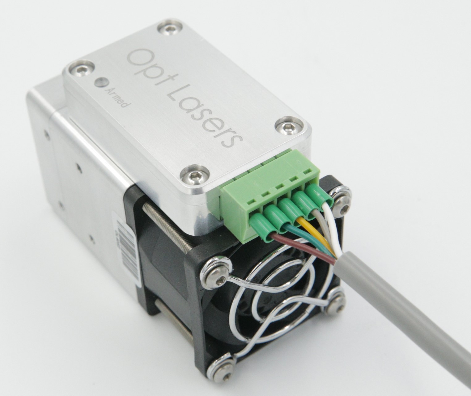
3. Connect the other end of the laser head.
Find the wire with a 5 pin euro connector and plug it into the laser head. For more information on the electrical input of the PLH3D-6W-XF+ head over to our Laser Head User Manual.
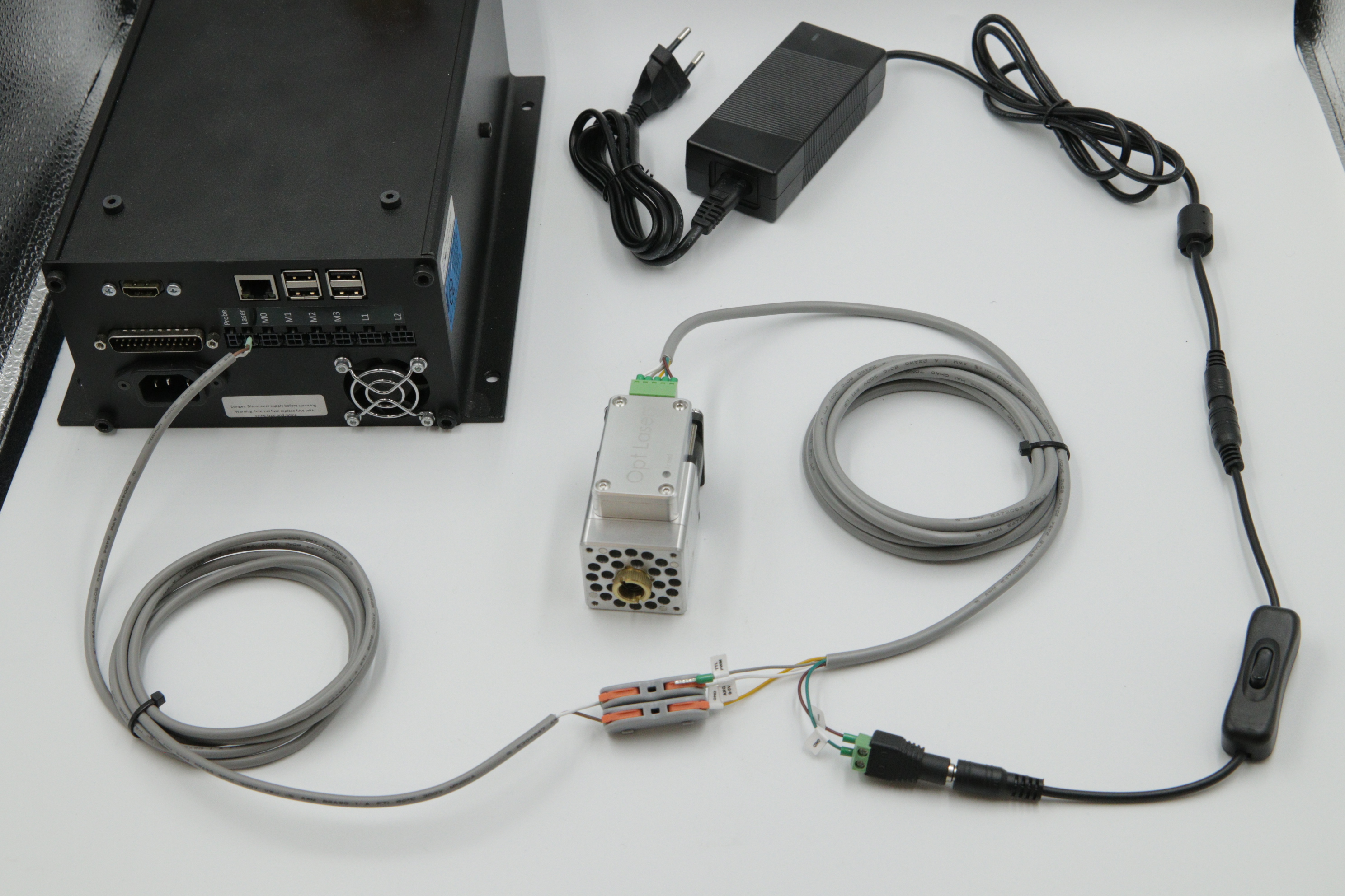
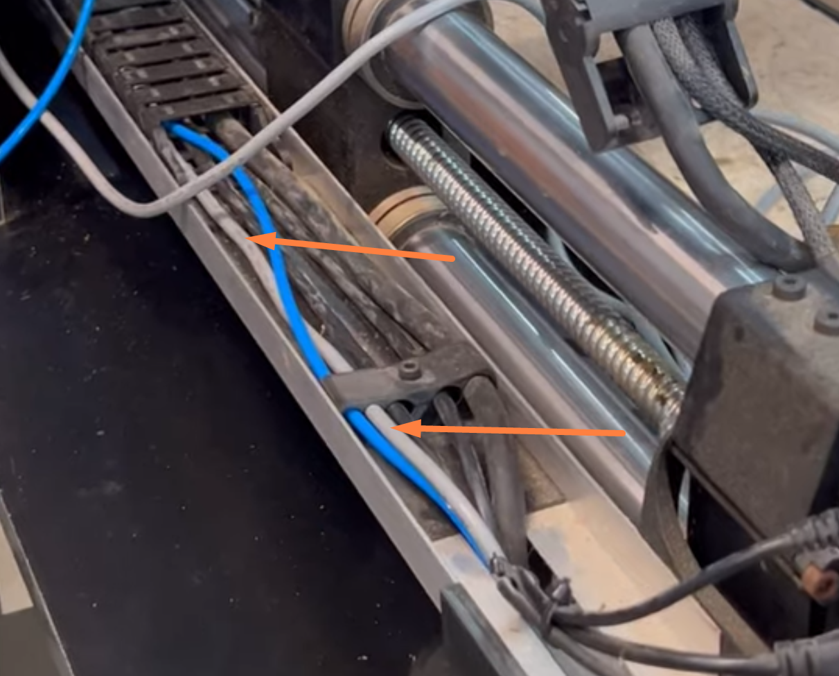
4. Connect the signal wire to your CNC controller
Start with passing and securing the Controller-Laser Head wire along drag chain by putting it through it or using zip ties. Below you can see example of cable management:
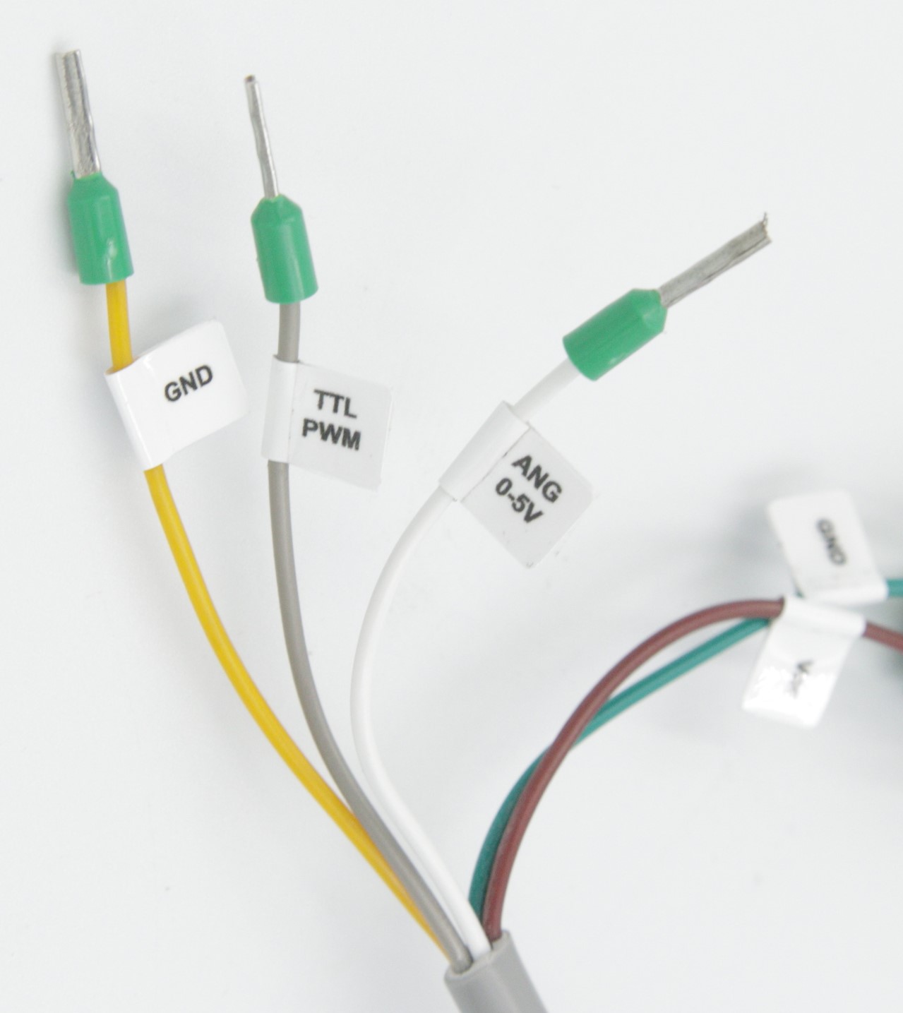
1. Connection with the universal wire only
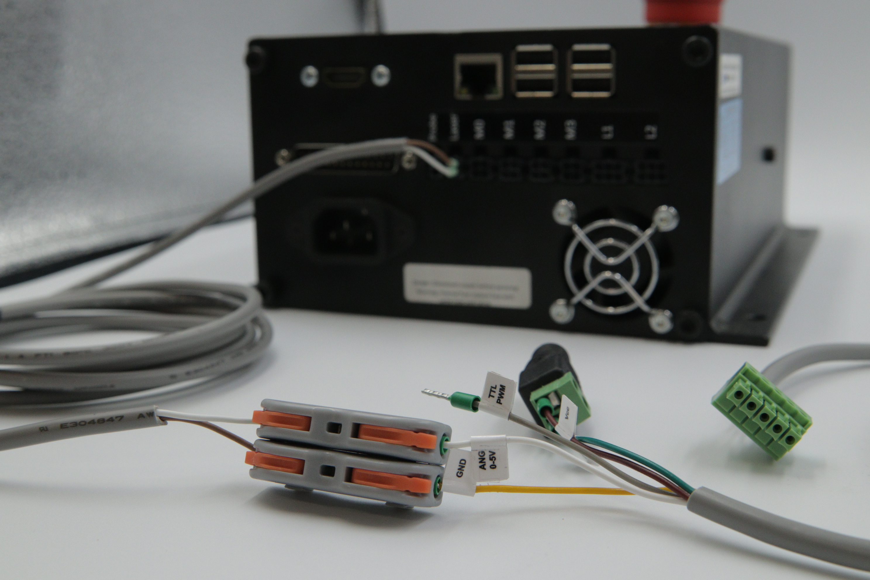
Connect the GND wire and either PWM or ANG 0-5V. Both are viable and specific connection depends on your controllers pin out. For more information look into our CNC Controllers Connection manuals, or contact us directly. Most of the controllers require only 2 connected wires, so depending on your choice ANG 0-5V or TTL/PWM will remain unused.
2. Connection with a controller-specific wire
Depending on the model of your controller, decide whether you will be using the TTL/PWM or ANG wires. Plug in the chosen one and the GND wires to the WAGO wire connector. To do so, lift the orange switch of the connector up, insert the cable and lock the cable with the orange switch. Kits sold to a specific controllers only need 2 wires, so after locking the selected signal wire in the connector, one wire will be left unused. Below is a picture of example of an connection with a Onefinity controller.
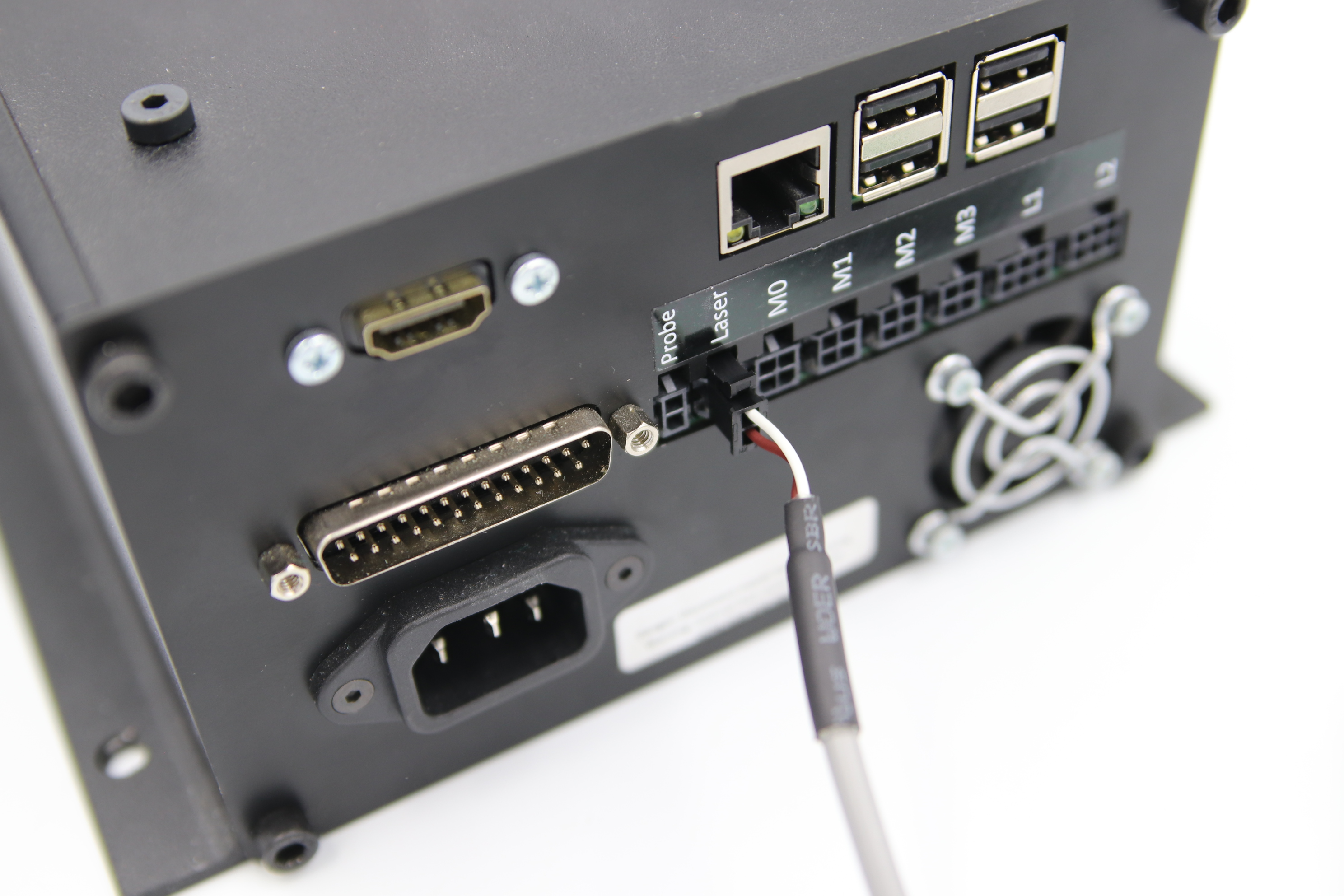
Then connect the controller wire according to the controller specific manual. For more information look into our CNC Controllers Connection manuals. Eco kits does not include adapter, but it is not needed for a functional connection.
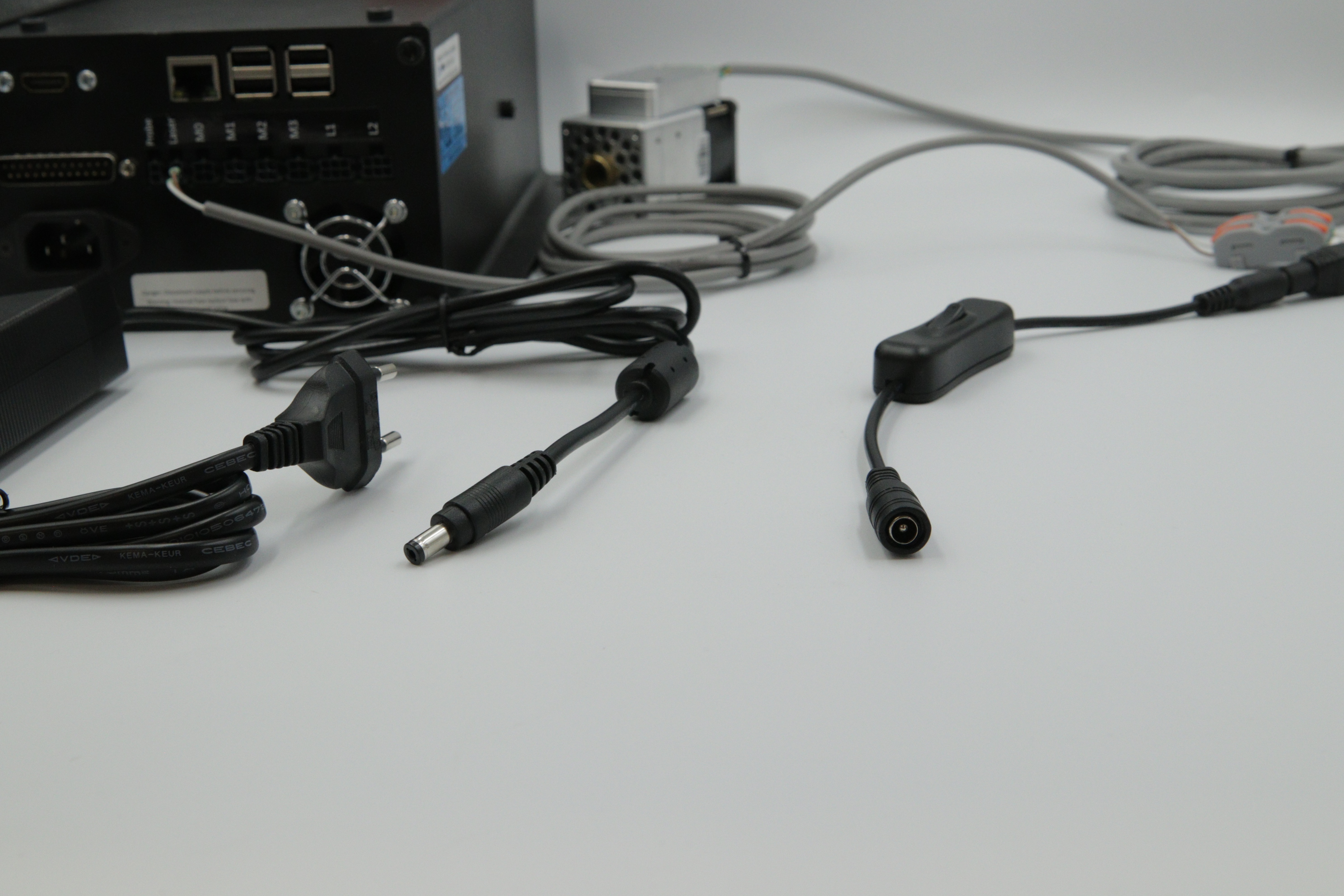
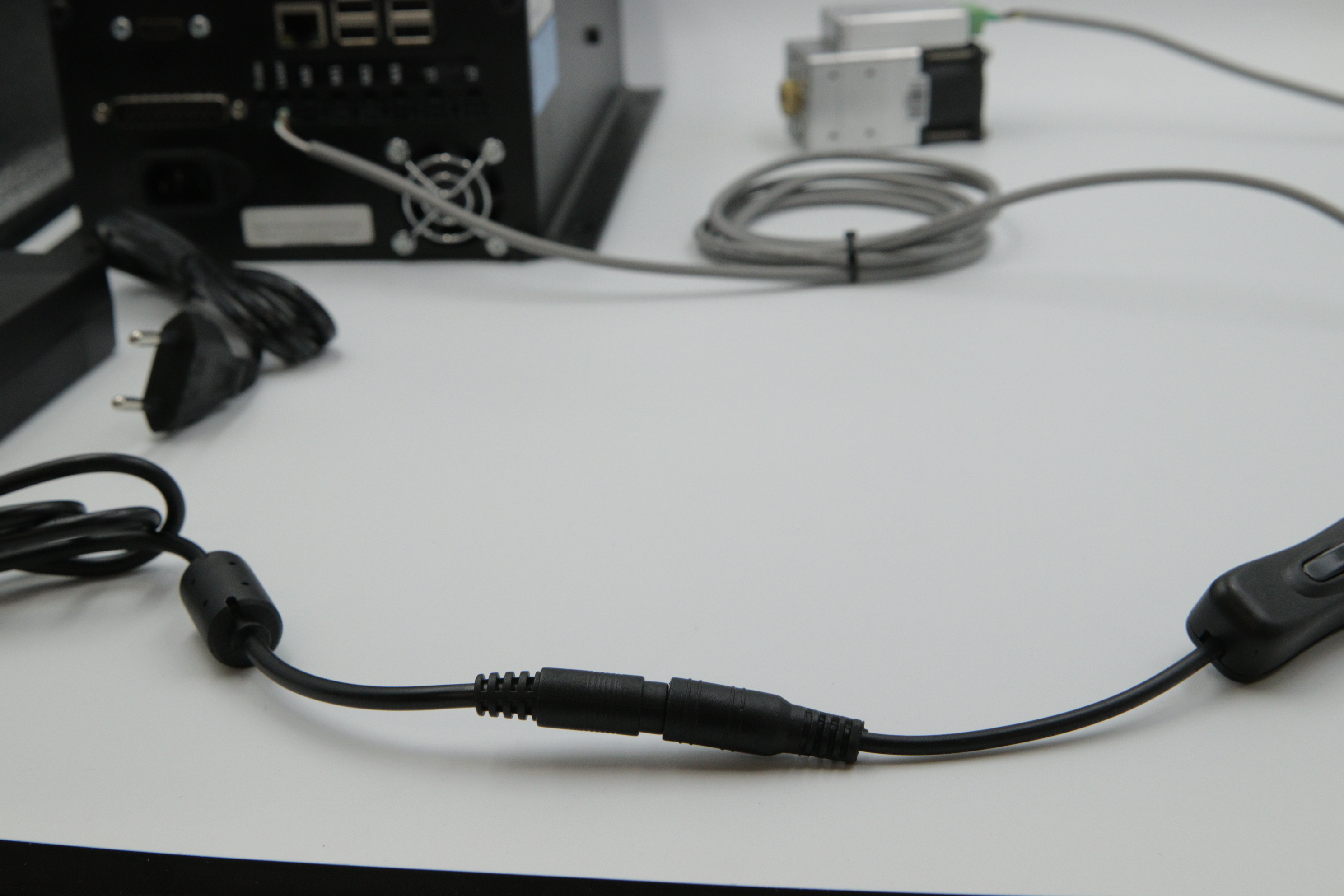
5. Connect Vcc and GND wires to the on/off switch adapter
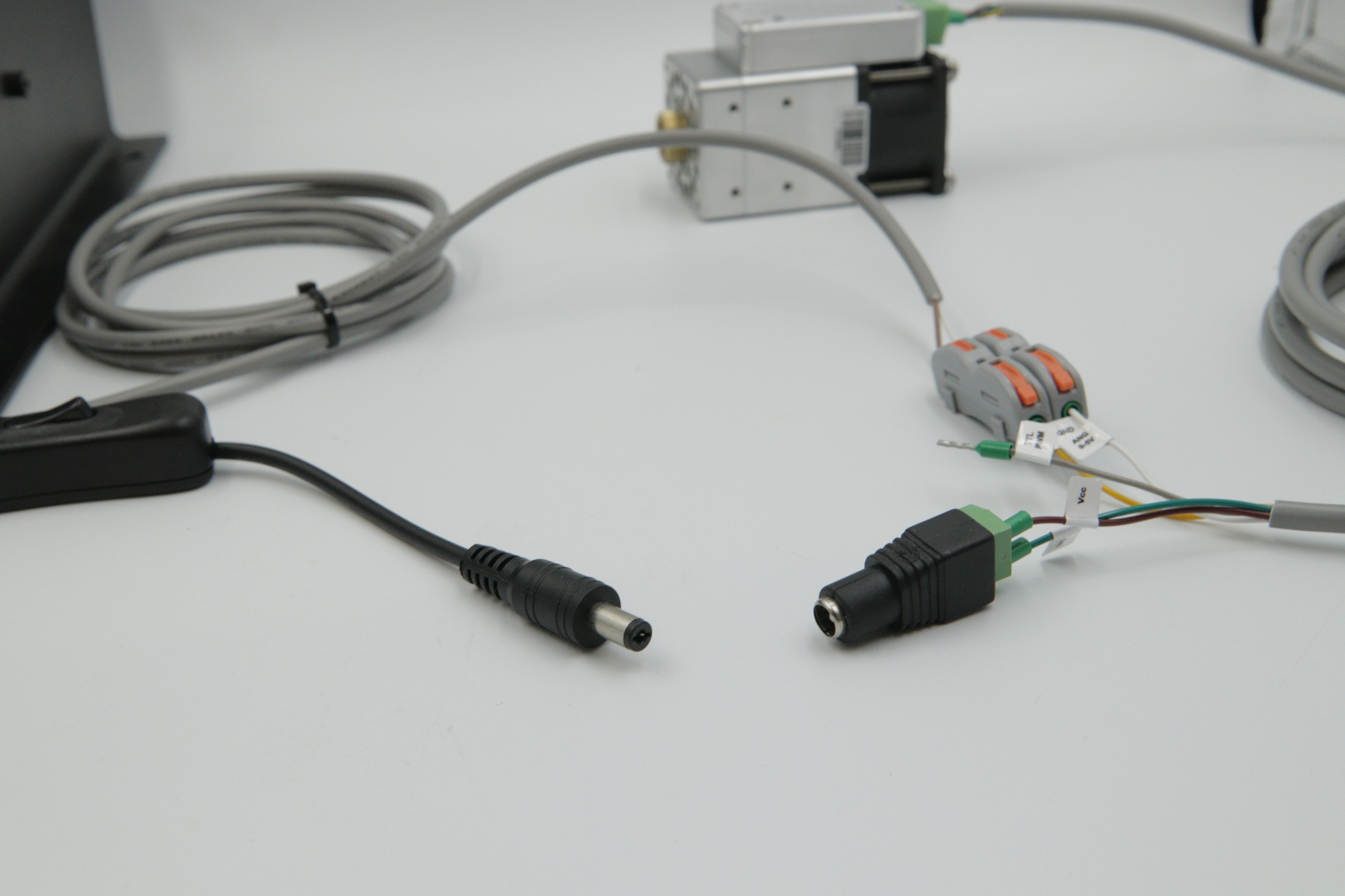
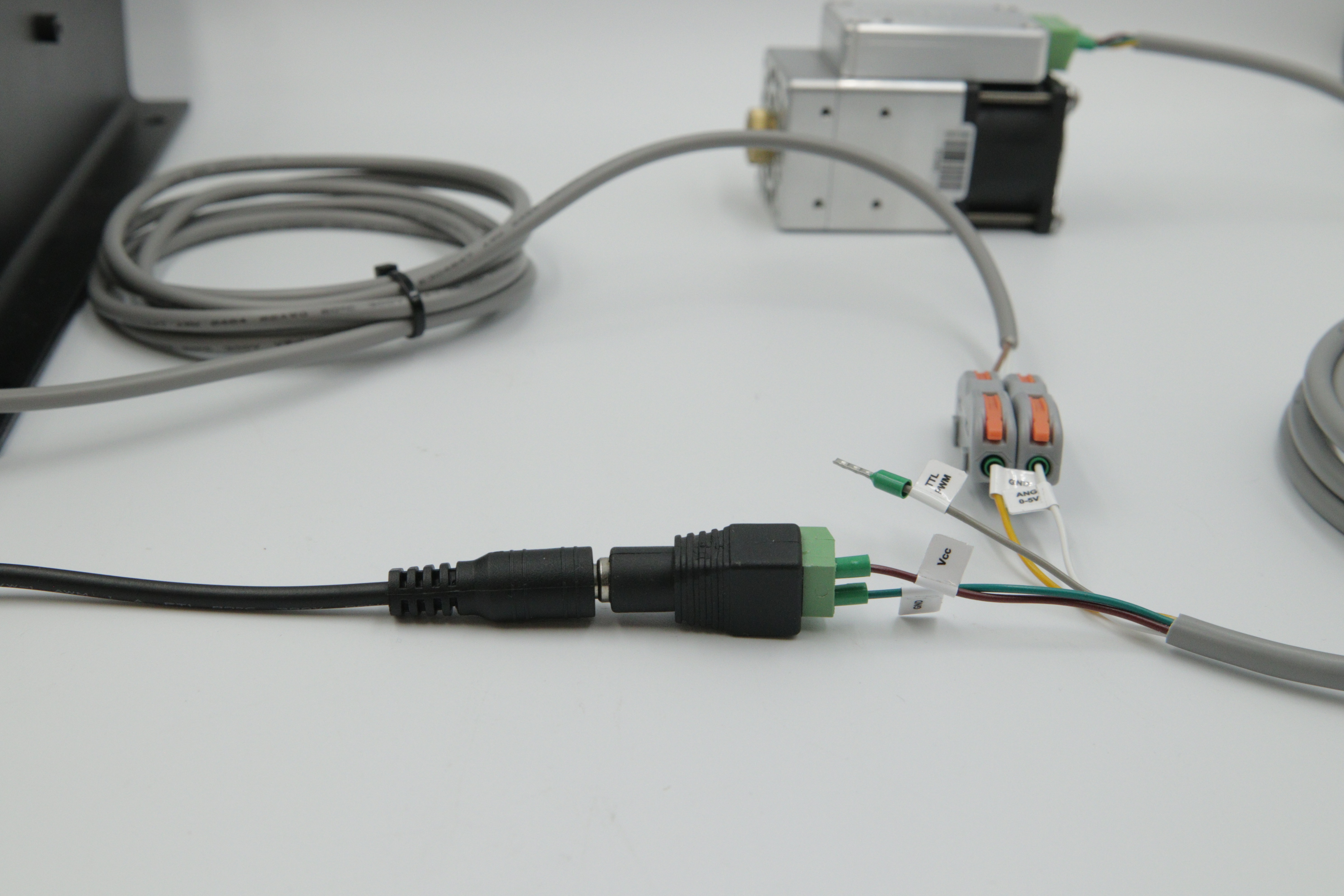
6. Connect the second end of the on/off switch adapter to the power supply end