Ortur Laser Master 2 Upgrade - Mounting Instructions
1. To mount the PLH3D-6W Series laser head, following tools are required, depending on the mounting option you choose:
- Small flathead screwdriver
- Hex Key H2.5
- Hex Key H3
- Torx 10 Key
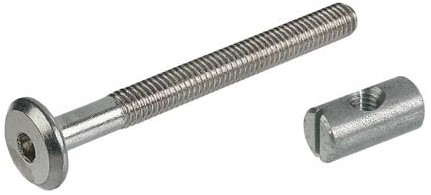
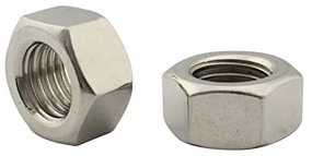
- Open-end wrench 8mm for M5 or equal nut or ratchet
- A few zip ties
- Soldering iron with small tip around 1 mm and a solder tin
- Wire Strippers
- Side cutters for zip ties to trim them
- Drillbit Ø3,5mm for the acrylic plate holes
- Vernier Calipers
- Scribing needle
- Stop angle
- Borehole punch
- An appropriate drill (depending on your size of the zip tie to open up the holes on the machine so that they can fit your zip ties in terms of size)
2. There are two basic ways in which you can mount the PLH3D-6W laser head on Ortur Laser Master 2.
2.1 Option 1 (Not Recommended): Mounting the laser head directly on the original acrylic board.
To use this option you have to unscrew the four M5 nuts together with the original laser head. Then you need to drill new holes in the black plexiglass and screw the PLH3D-6W laser to it. A pattern that works well is averaged out on the acrylic plate. You have to measure the size of your acrylic plate and subtract 24 mm from the value obtained (as the distance of the laser head holes is vertical). Example: Plate size: 75.7 mm - 24 mm = 51.7 mm which gives 28.85 mm (51.7 mm/2) from the side. The following dimensions are appropriate:
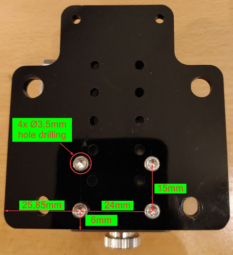
To fix the laser head, you have be aware that the acrylic plate holes are covered and too close to the laser. As a result, you should use distance holders. The easiest way is to utilize M3x20mm screws. You will need to insert spacers between the laser head and the acrylic plate. You can for example use three M4 nuts as M3x20 screws fit perfectly with them. You will need approximately 10 mm distance on each hole.
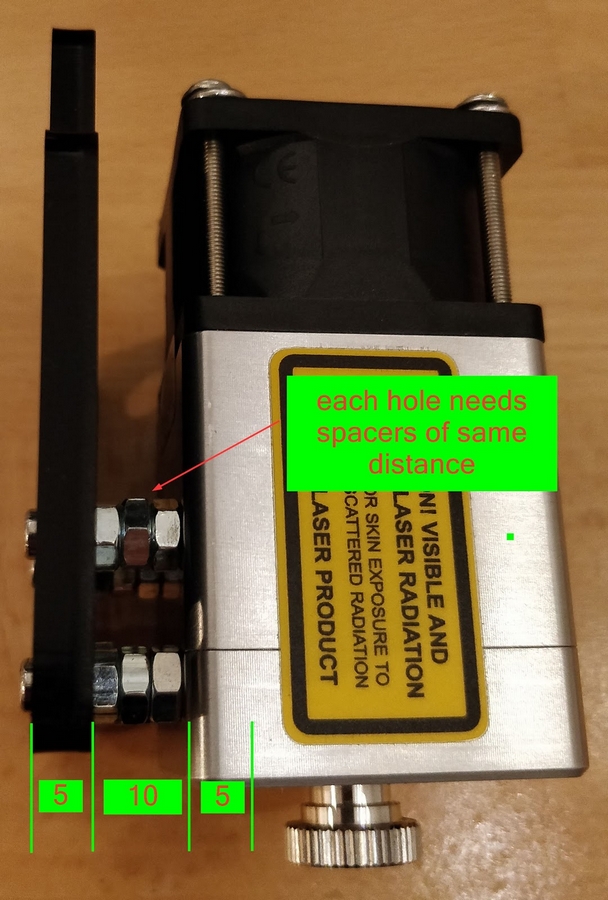
The acrylic plate is 5 mm thick. 5 mm acrylic plate + 10mm spacer + 5 mm thread in laser head yields 20 mm thread length for the fixation screw. Note that you can use any kind of rigid spacer that is around 10 mm long and that it doesn't need to be precisely 10 mm You will need four identical ones.
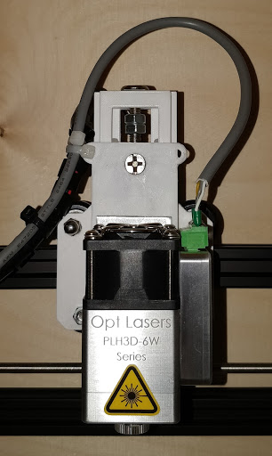
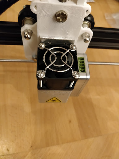
Once assembled, it should like this:
Important: This assembly method is not recommended as it fixes the laser head at a specific distance. Doing so will require you to either use a height adjustable table or turn the lens (which affects the power density at the focal spot) in order to get the appropriate working distance for laser cutting and engraving. The optimal focus is 60 mm from the face of the laser head. If you choose to go forward with this method and turn the lens with the lens knob (until you get the smallest possible beam spot on your workpiece), you would have to adjust the lens for each and every workpiece that differs in height from your previous one.
2.2 Option 2 (Recommended): Mounting the laser head via Height Adjustment Add-on.
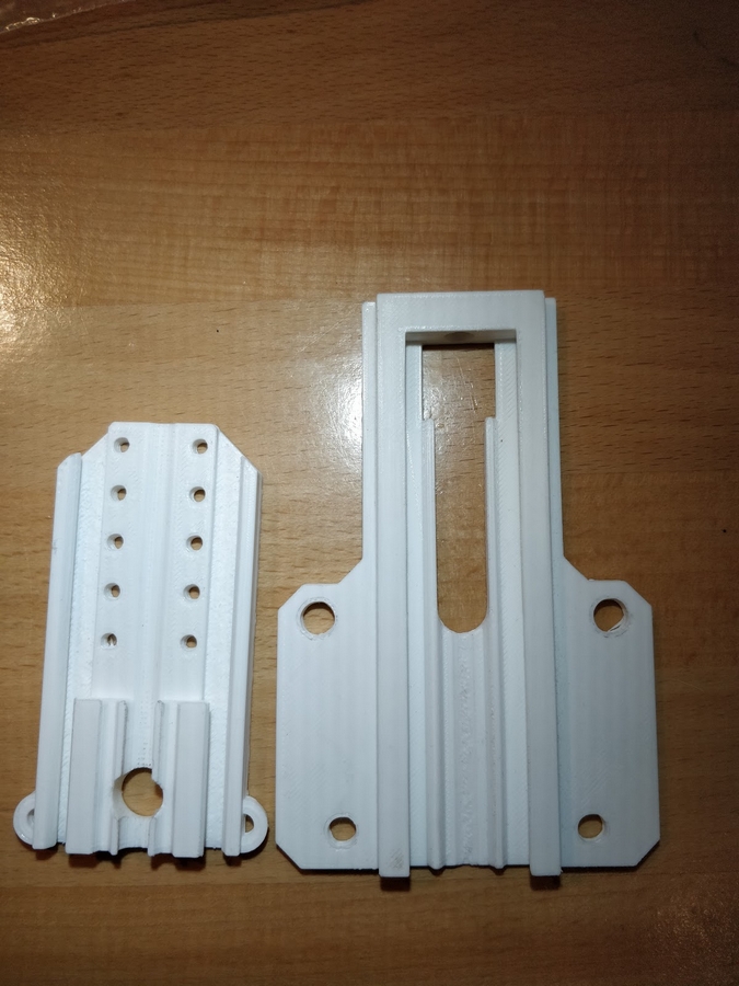
This method uses a height adjustment tool that is printable with a 3D printer and which allows to move your laser head up and down with an allen screw to get the 60 mm working distance. This Height Adjustment Add-on Tool can be found on Thingverse under the name Height Adjustment Ortur Laser Master 2, Höhenverstellung Lasermaster 2 (uploaded by PLAY3Rone977).
This method proceeds in a similar way to Option 1. You will also need two pieces of M6 nuts to lock the Add-on Tool in place as well as a set of M6 cross nut bolts and approximately 75 mm long M6 screw for the movement mechanism.
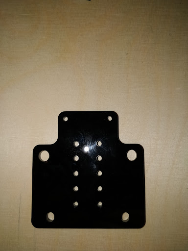
To mount the laser to the Add-on Tool, you will need an adapter plate that is suitable for your needs in terms of the depth. This manual shows the application of an 80 mm long Aluminium plate.
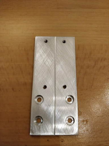
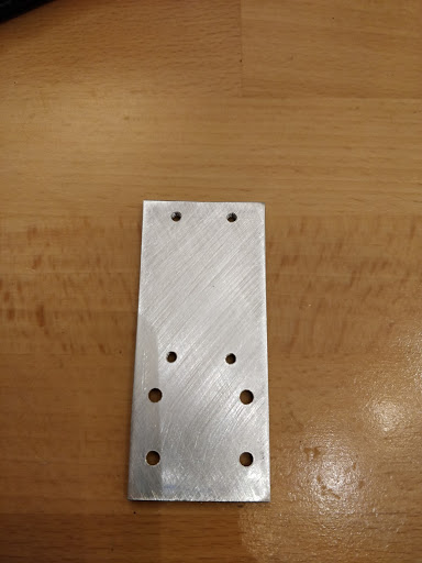
The laser head mounting holes pattern is 24 mm by 16 mm.
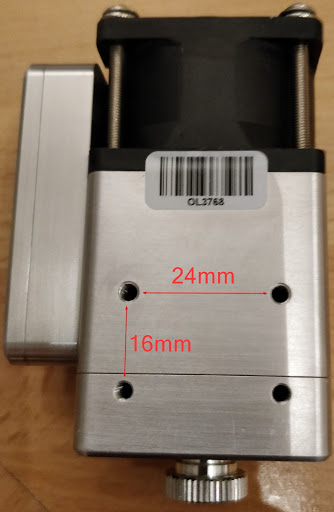
The remaining holes are M3 threads with a 16 mm by 10 mm pattern. They allow to screw the Aluminium plate to the 3D-printed slider.
Once the Height Adjustment Tool is properly assembled, you can mount it to the bolts on ORTUR.

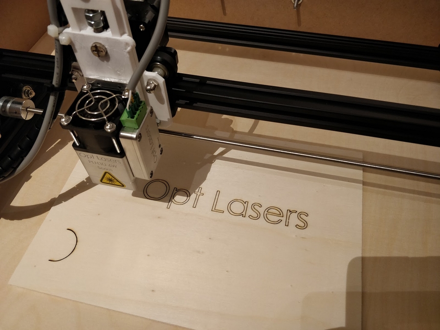
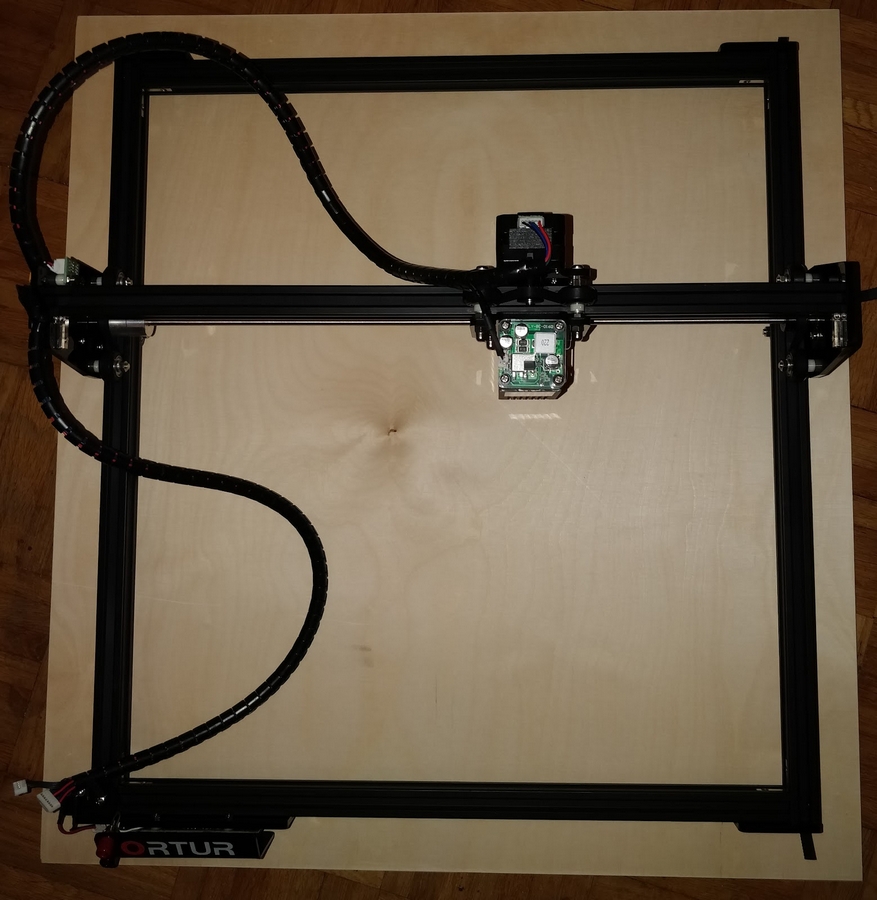
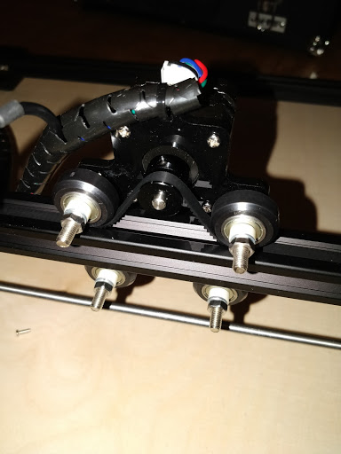
3. Your finished mechanical system should look like this:
Option 1
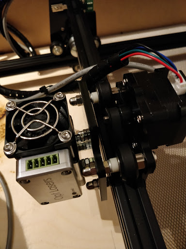
Option 2