Ortur Laser Master Upgrade - Wiring Setup
1. Unpack the Opt Lasers PLH3D-CNC Adapter.
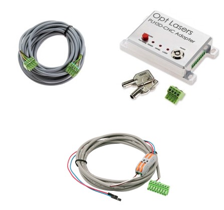
2. Plug one end of the PLH3D-CNC Adapter to Laser Head Cable to the laser head input socket. Next, attach the cable to the mount with a zip tie.
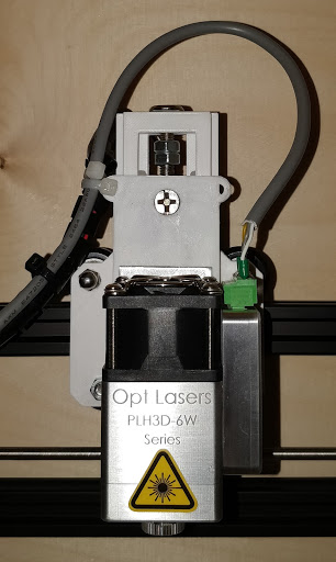
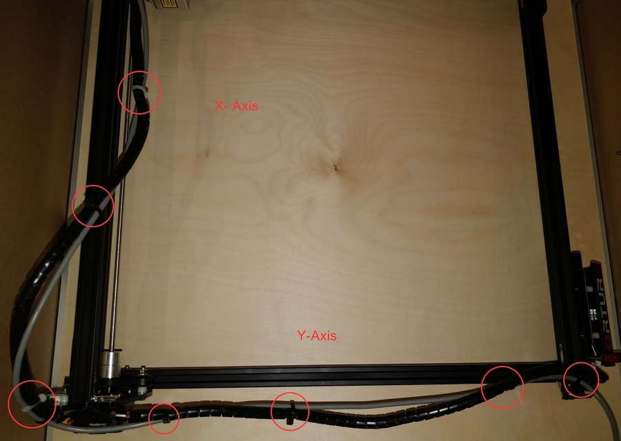
3. Remove the cable for your previous laser head. Because of the thickness of the cable you cannot mount it directly inside the cable sleeve. Secure the new cable with zip ties on the outside of the sleeve and then with the dedicated zip tie holes on Ortur Laser Master 2.
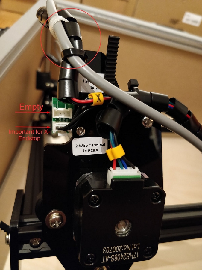
The socket for the removed laser cable is empty. Please ensure that the lower terminal with black wires is firmly connected. This is important for the X-Endstop.
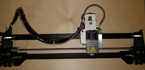
4. For the nest step, run the cable along the X-Axis and Y- Axis cable sleeve.
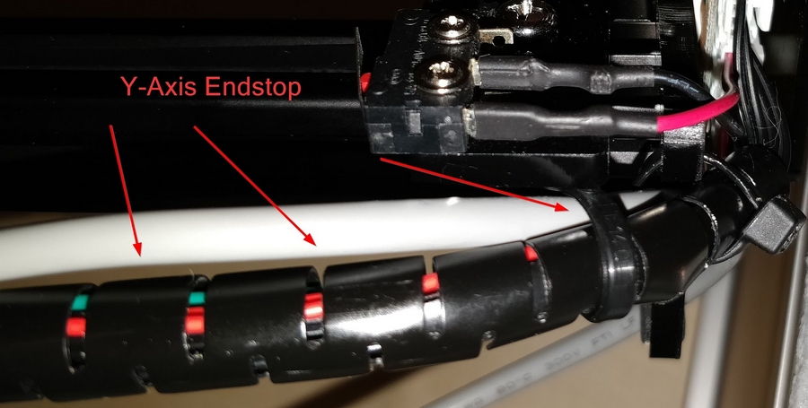
5. During the process of fixing the laser head cable along the Y-Axis, please make sure you do not block the limit switch.
5. Double-check the Ortur Laser Master 2 working area for potential collisions with the PLH3D Laser or cables.
IMPORTANT: This step must be carried out BEFORE the electrical commissioning of the Ortur Laser Master 2 as the machine performs an automatic reference run along the axes at the launch, otherwise collisions and damage may occur.
You can push forward or pull the X-Axis frame by hand until it hits the limit switch. Check if the limit switch can be reached.
Check whether the limit switch can be operated without a collision between the laser head, mounted on the X-Axis, and the front panel of the Ortur Laser Master 2. For this purpose, the Y-Axis can be moved from left to right over its entire length. You should verify manually that the machine can move the laser head over the entire area without any collision with any components.
You can mount the magnetic nozzle on the laser head to check if the machine can home without collision while the nozzle is mounted.

If there are potential collisions, the screw holding the Y-toothed belt can be loosened and relocated together with the Y-Axis limit switch. The new position should give the laser head sufficient space to move without any collision.

6. For the next step, you need to take out the Ortur Laser Master 2 control board to connect the PWM and GND signals.
First of all, you have to unplug all cables on the left:
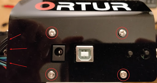
Then, remove all four screws from the front panel to remove the PCB board. Be careful not to touch and/or damage the PCB board.
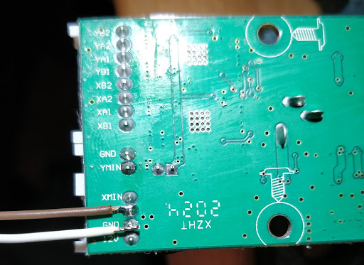
7. Once you have the Ortur Laser Master 2 control board, you need to solder the PWM and Ground wire from the Signal Cable to it.
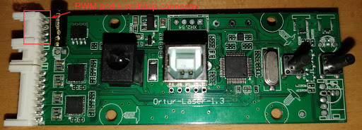

To solder the wires, you need a steady hand and a small tip on your solder iron. Please be careful and ensure you do not short circuit the other pins. Once you have soldered the wires, verify that there is no unwanted connection to other pins.
The end result should look like this:
Once you have finished you can carefully place the control board back inside the Ortur Laser Master 2 control box and reconnect the wires you unplugged at the beginning of this step.
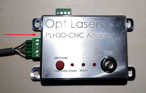
8. Plug the other end of the Adapter to Laser Head Cable into the socket on the left hand side of the PLH3D-CNC Adapter.
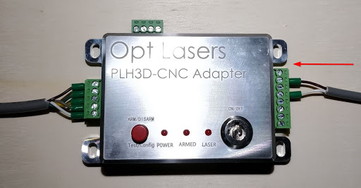
9. Plug the other end of the Signal Cable into the socket on the right hand side of the PLH3D-CNC Adapter.
Please bear in mind that your Signal Cable is soldered to control board. Please ensure that you use zip ties so that the Signal Cable doesn't move, because it could potentially detach the soldered wires from the control board and/or damage the Signal Cable.
10. Put on your Laser Safety Glasses. Ensure nothing unintended is left in the path of your laser. Ensure that the Adapter is off.
11. Insert the power cord into the PLH3D-CNC Adapter and plug the opposite end into your outlet.
