Stepcraft Laser Upgrade with PLH3D-6W-XF+ - Setting the Working Distance
The PLH3D-6W Series laser head ships with the High-Resolution Triplet lens installed and adjusted to focus at 60.0 mm (measured from the front-face surface of the laser head to engraving plane). This focal distance has well-optimized focal spot size to output light power ratio which is suitable for many engraving and cutting applications. We recommend keeping the focal distance of the laser set to the default of 60.0 mm as a starting point.
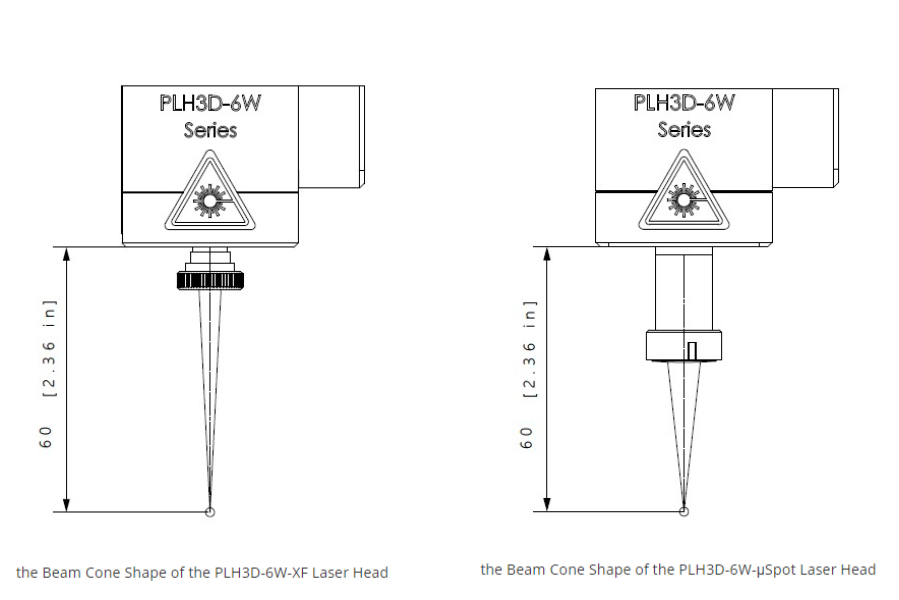
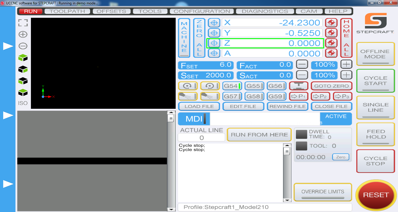
Mount the laser head on the CNC machine with front side (side on which lens is installed) pointing towards engraving material. Note: Make sure that the laser head is in stable position and does not move under influence of external forces. Engraving material should be at stable position as well, it should not move during engraving. Using your CNC machine, set laser head position at 60 mm measuring from the front side of the laser head to engraving material. Hint: Use a caliper or 60mm long piece of material to measure precisely the distance. After setting the position zero the Z-axis on the CNC machine and use the laser in XY plane without changing the Z value.
Some engraving applications may require small focus spot, i.e. high-resolution engraving, detailed engraving. PLH3D-6W Series engraving laser has adjustable focal length and exchangeable lens. This future allows it to fulfill broad range of engraving applications. Shorter focal length of the engraving laser produces a smaller beam spot (higher power density).
You can adjust focus spot distance from the front of the engraving laser by rotating the lens clockwise or counterclockwise. Note: it is necessary to ensure that the mounted lens is sufficiently deep inside the laser head, so the lens does not move before powering on the unit.
Once you changed the position of the lens use your CNC machine to find where is the focus spot. Using the methods described above calibrate the engraving laser head's position.
- Coarse adjustment:
- Set current position as a zero position in your CNC software.
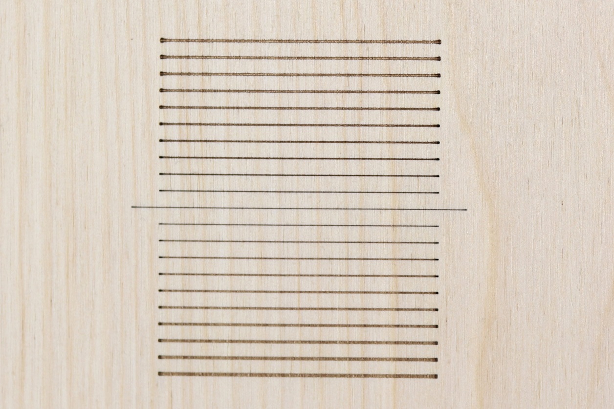
- Engrave “zero position” line on the engraving material. Hint: make this line longer compares to the next engraved line, it’s going to be easier to find “zero line”.
- Engrave (on the engraving material) 10 lines with step 1 mm in the positive direction of Z-axis and 3 mm step in X-axis.
- Go back to zero position.
- Engrave (on the engraving material) 10 lines with step 1 mm in the negative direction of Z-axis. and 3 mm step in X-axis.
- Inspect engraved lines, find the thinnest engraved line.
- Count how many lines away is the thinnest line from “zero line”, and in which direction it is placed. Let’s consider case when the thinnest line is located 5 lines from zero line and in positive direction of X-axis. In such a case calibration parameter is +5mm.
- In the CNC software, move “zero position” of the laser head by calibration parameter.
- Fine adjustment:
To obtain the highest power density, which results in the better engraving performance, we recommend making fine adjustments to the distance of the laser head and the engraving material. This adjustment should be done after performing coarse adjustment.
The process is similar to the coarse adjustment process expect steps in Z-axis, they are smaller to make adjustment precise.
- Set engraving laser head at a zero position, which must be calibrated by know.
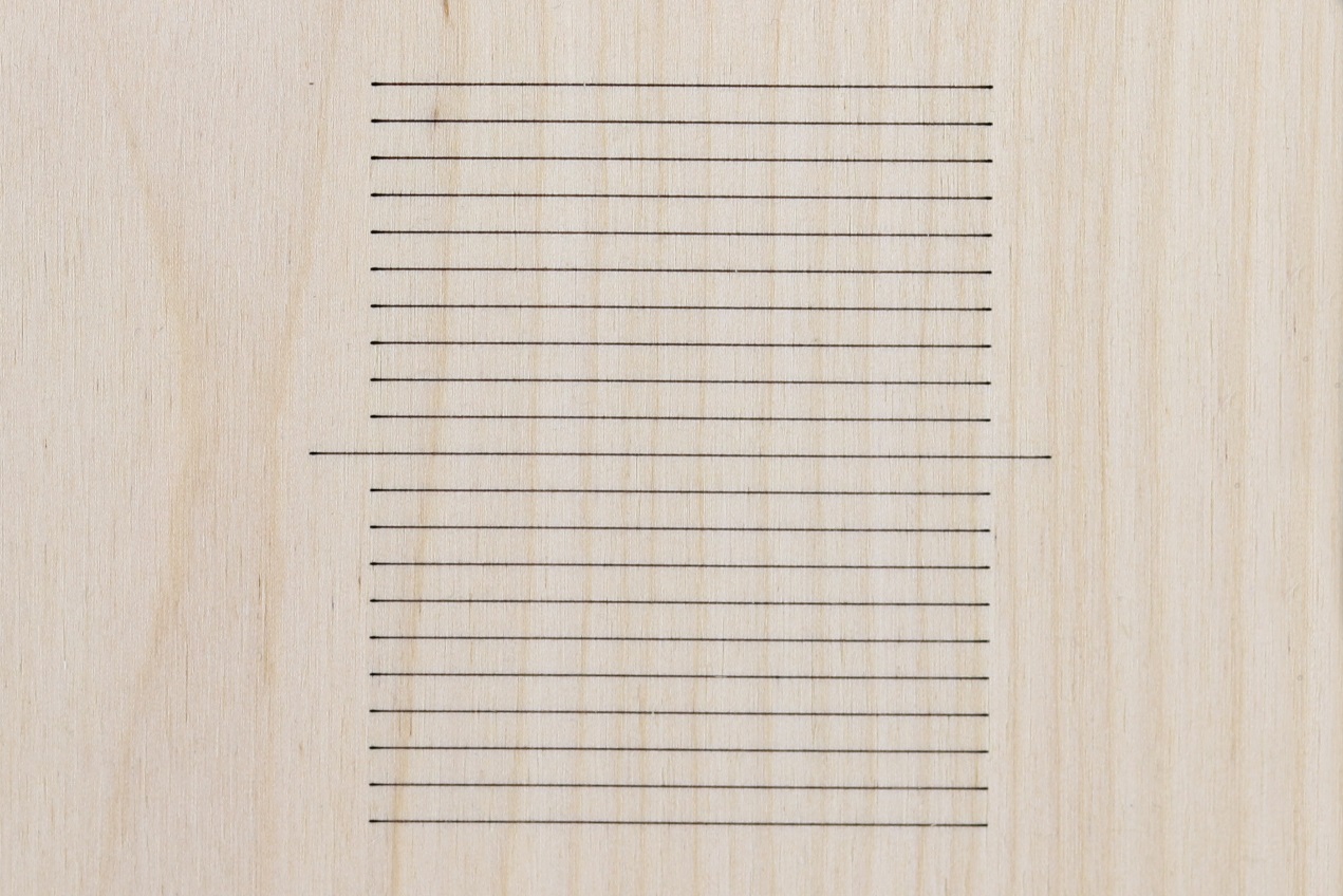
- Engrave “zero position” line on the engraving material. Hint: make this line longer compares to the next engraved line, it’s going to be easier to find “zero line”.
- Engrave (on the engraving material) 10 lines with step 0.1mm in the positive direction of Z-axis and 3 mm step in X-axis. We recommend engraving lines with 50mm length, it is easier for eye to compare thickness of a line on longer range.
- Go back to “zero position”.
- Engrave (on the engraving material) 10 lines with step 0.1 mm in the negative direction of Z-axis. and 3 mm step in X-axis.
- Inspect engraved lines, find the thinnest engraved line.
- Count how many lines away is the thinnest line from “zero line”, and in which direction it is placed. Let’s consider case when the thinnest line is located 2 lines from zero line and in negative direction of X-axis. In such a case calibration parameter is -0.2 mm.
- In the CNC software, move “zero position” of the laser head by calibration parameter.
Adjusting the z-axis in a newly purchased laser head
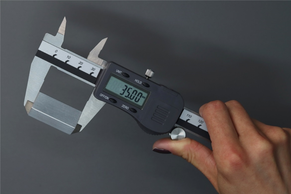
- Since our laser heads are factory-set to have a focus at 60mm distance, adjustment of the z-axis distance can be made easily using a 35mm height block of metal, wood or plastic.
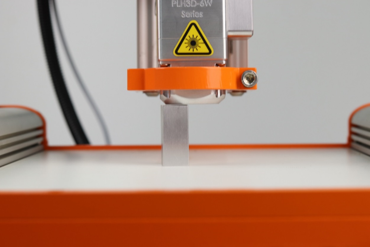
- Place the block under the mounted laser head and carefully reduce the distance between them. (Note: if you would like to cut material, put the block directly on the Stepcraft’s CNC machine table. For engraving, put a material on table first and the block underneath it.)
- Place a piece of paper between the nozzle of the laser head and the block. Using the slowest possible speed move down the laser head until you will not be able to move the paper easily.
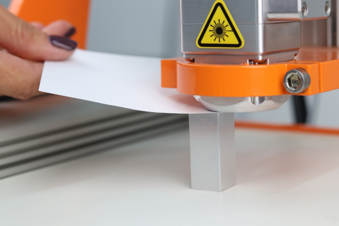
- Make this position of z-axis as your zero position.