Duet Software Setup for Pre-3.0 RR Firmware - Ooznest WorkBee Laser Upgrade
Firmware Configuration
Using the WorkBee PLH3D Mount and Magnetic Docking Station makes connecting the laser head effortless, but also decreases the available workspace slightly. To prevent damage to the laser head mount, it is necessary to set the X-axis minimum to 25mm.
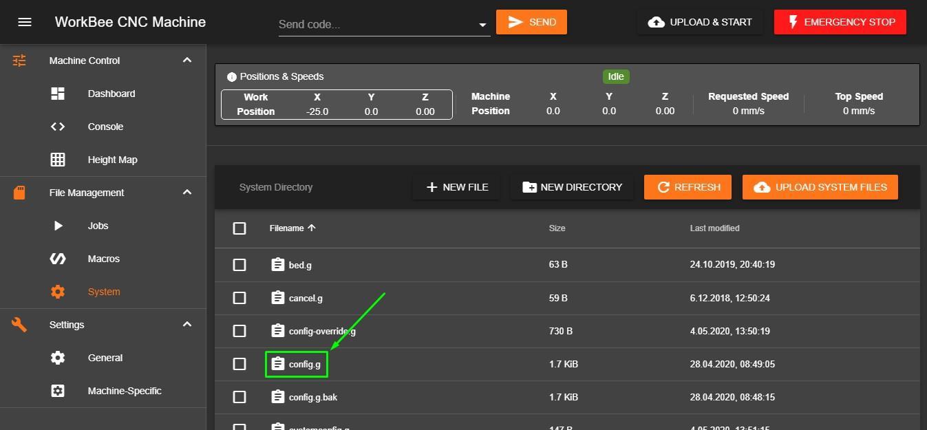
- Start WorkBee Control. In File Management/System open config.g.
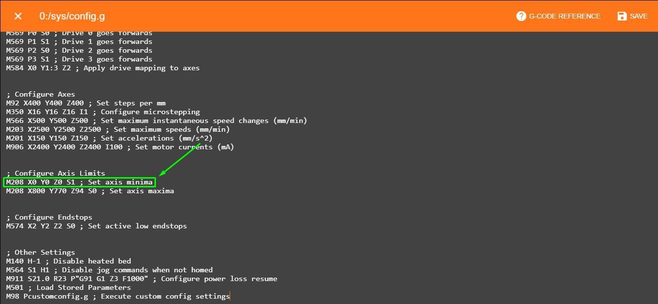
- Copy the G-code line that sets the axis minimum.
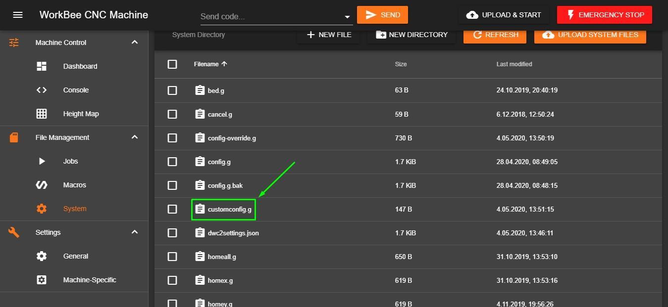
- Close config.g without saving and open customconfig.g.
- Paste the copied command and change the X value to 25. Save changes.
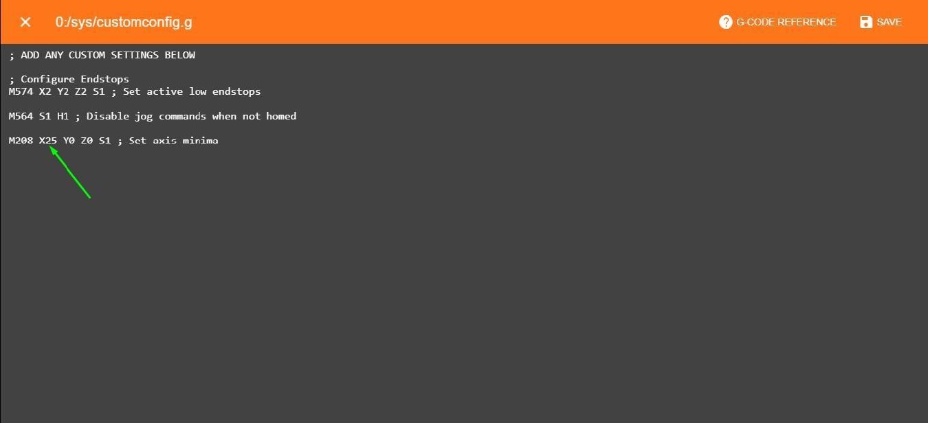
Now, your X-axis minimum is limited to 25 mm (in machine coordinates). Remember this when the laser is not in use. Set working coordinates only when the machine position in the X-axis is equal or higher than 25.
When a PLH3D-6W laser head is mounted, an additional 50mm in the X-axis has to be added. So the minimum limit in this axis will be 75mm.
Generating G-code
To cut or engrave, it is necessary to generate the appropriate G-code using the following commands:
|
M307 H3 A-1 C-1 D-1 |
Disable Heater output on pin #8 (HEATER3) |
|
M452 P3 R255 S1 F1000 |
Enable Laser mode on output 3 (HEATER3), with max PWM value 255, laser power (S parameter) is sticky across G1 commands and a PWM frequency is 1000 |
|
M3 |
Laser ON |
|
M5 |
Laser OFF |
|
SXXX |
PWM duty where XXX is number between 0 and 255 (e.g.: 0 = 0% and 255 = 100%) |
The first three commands should be placed at the beginning of the G-code file (in the header). The fourth command should be at the end of file (in the footer). The “S” command has to be at least in every line where laser power is being changed (except G0 lines, because G0 automatically turns off laser). To see a G-code example, please refer to Appendix 1.