Ooznest WorkBee Laser Upgrade - Mounting Setup
Setup Hardware
To mount the PLH3D-6W Series laser head, the following tools are required:
- Small flathead screwdriver
- Hex Key H2.5
- Hex Key H3
- A few zip ties (potentially)
Mounting Setup
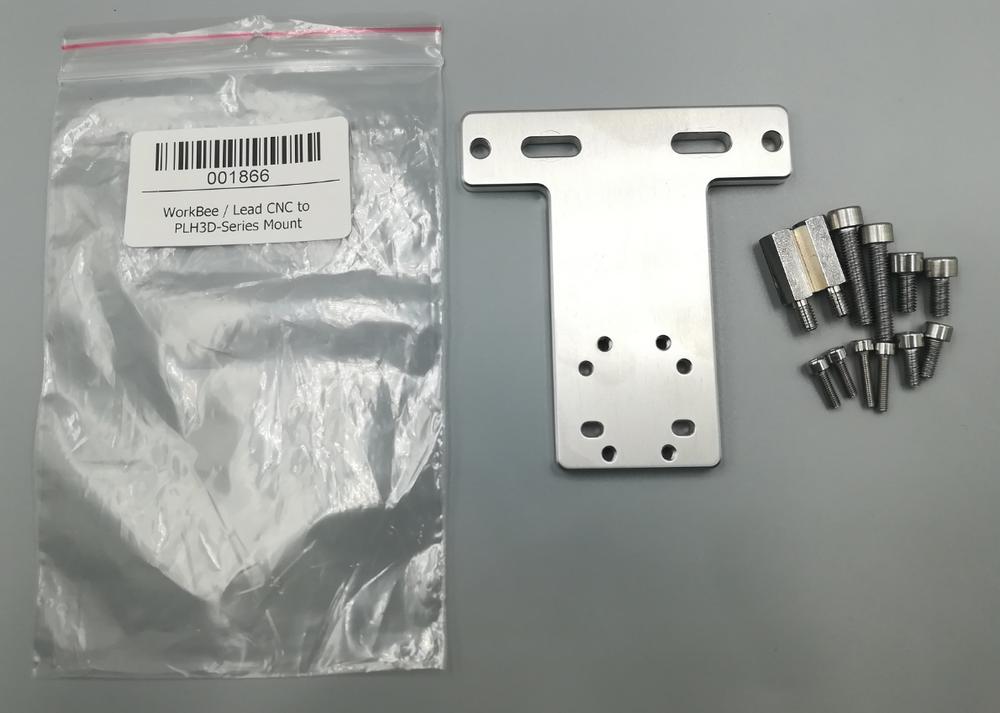
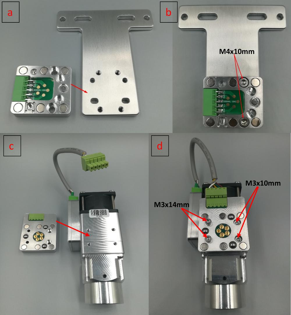
- Unpack the WorkBee PLH3D Mount. All necessary screws have been included.
- Unpack the LaserDock Magnetic Docking Station.
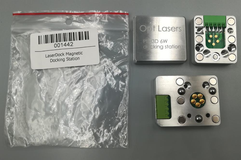
- Screw one side of the docking station onto the LWorkBee PLH3D Mount and then sandwich the laser head between the two parts of the docking station as depicted in the steps “a” to “d” below. Finish by screwing the second element of the docking station onto the laser head.
A detailed video instruction for the whole installation process can be found on Youtube:
Make sure to subscribe to our Youtube channel for exciting first-hand news and video guides.
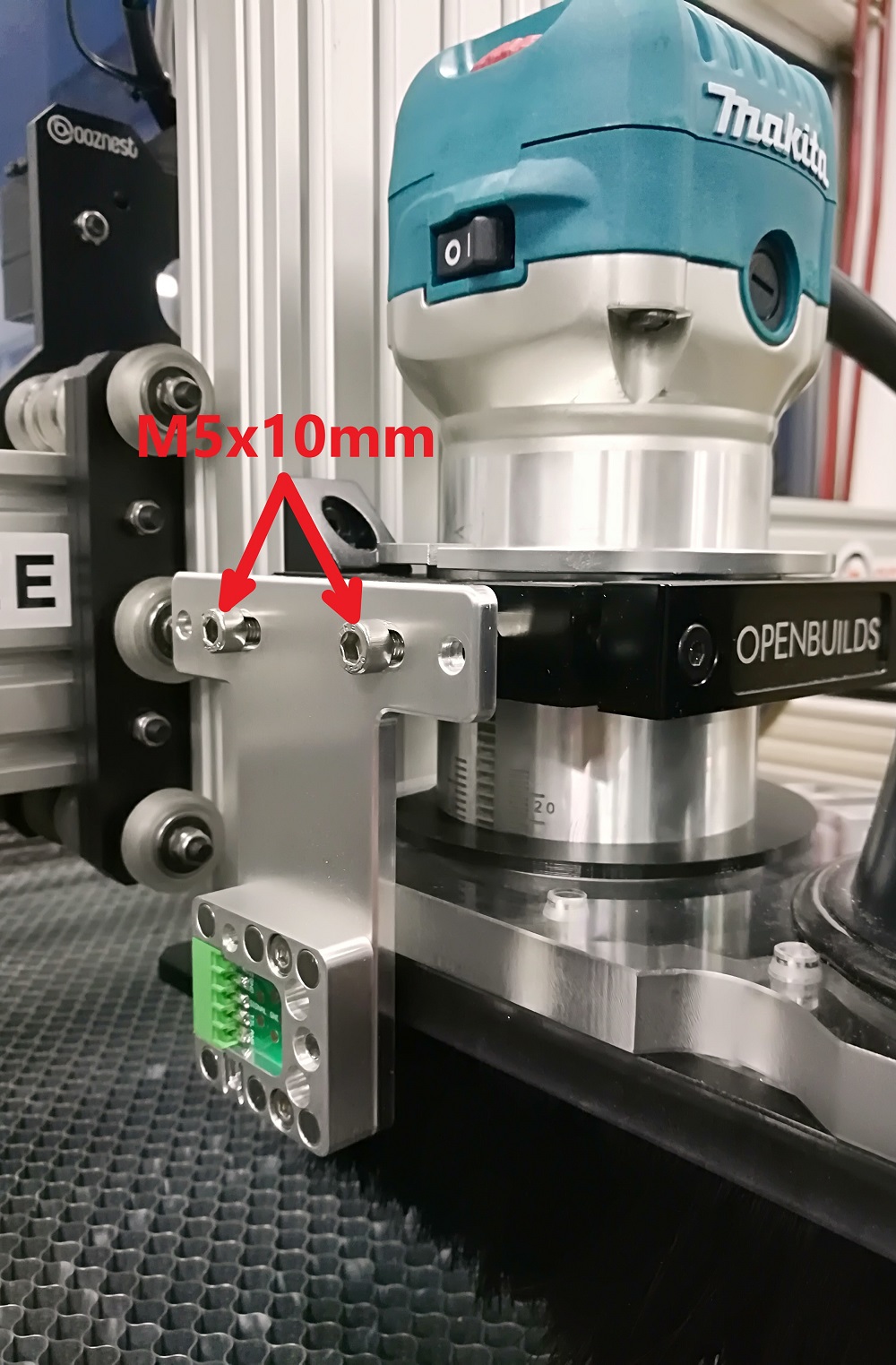
- Use an M5x18mm spacer to be able to install the laser mount without removing the dust shoe (possible only for mounting on the left- and right-hand sides). Mounting the docking station on the left-hand side is the recommended option, because, in this scenario, the laser cable will not face the user. Nevertheless, both left- and right-hand side mounting will decrease the workspace.
![]()
- Use an M5x10mm screw to screw the WorkBee PLH3D Mount onto the spacers.
Wiring Setup
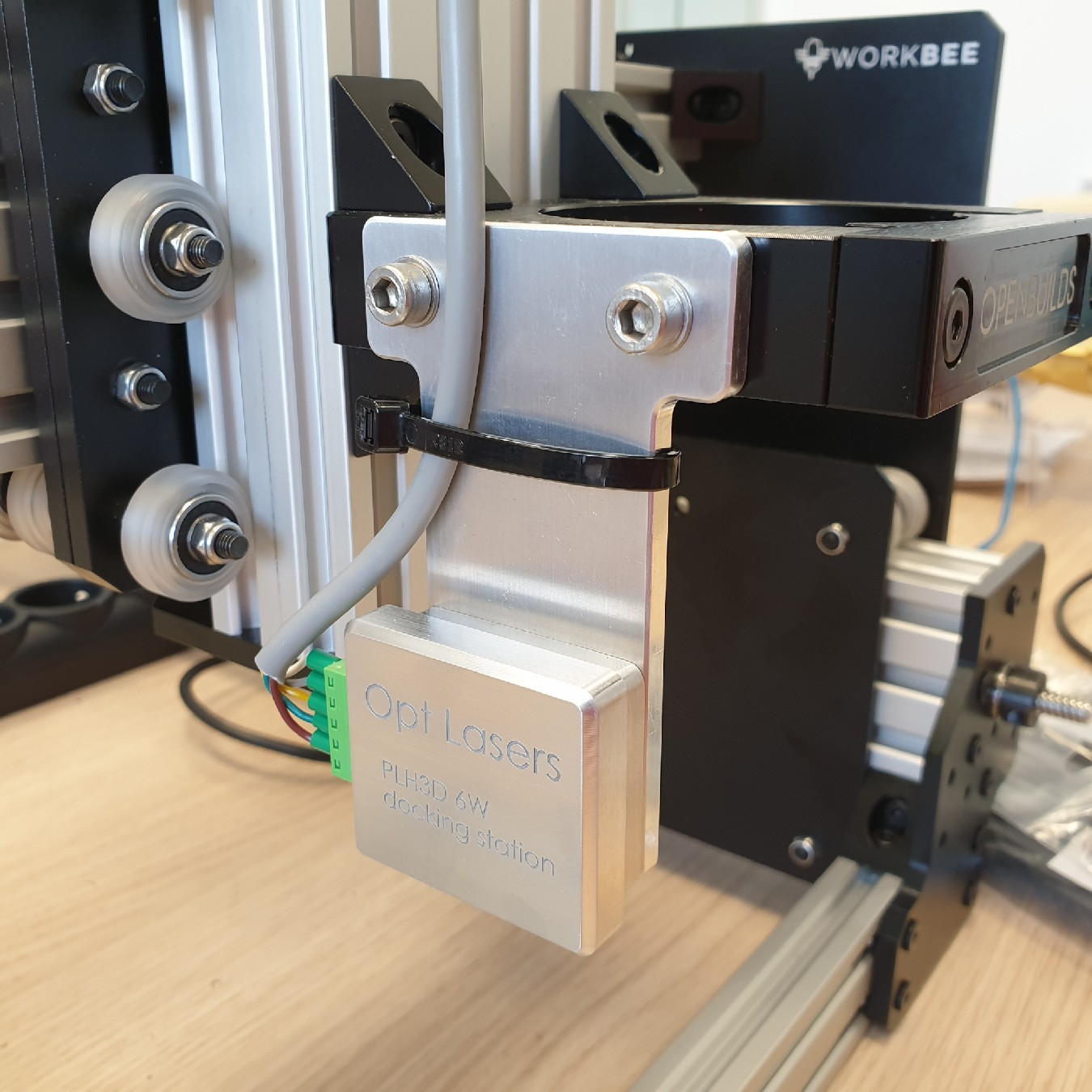
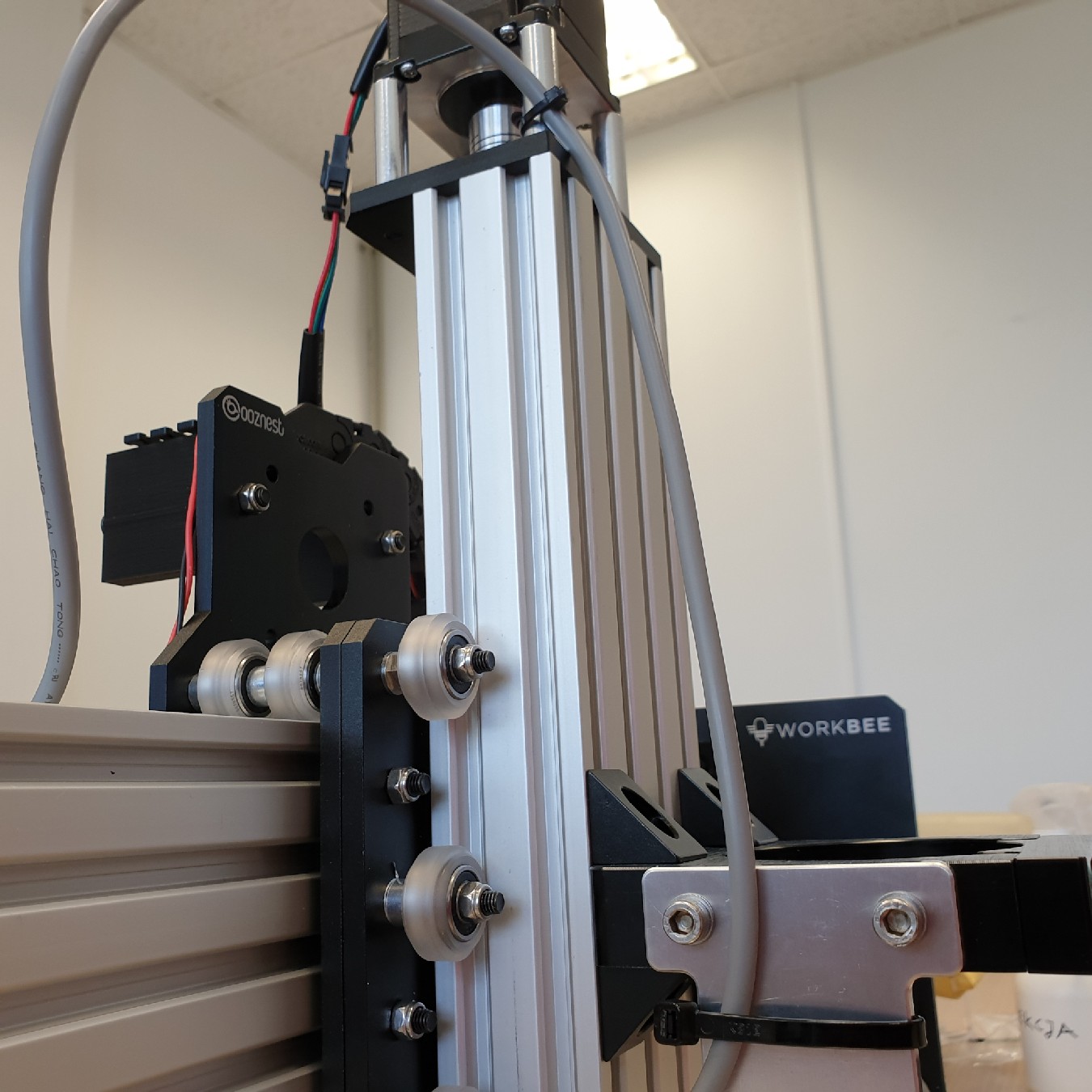
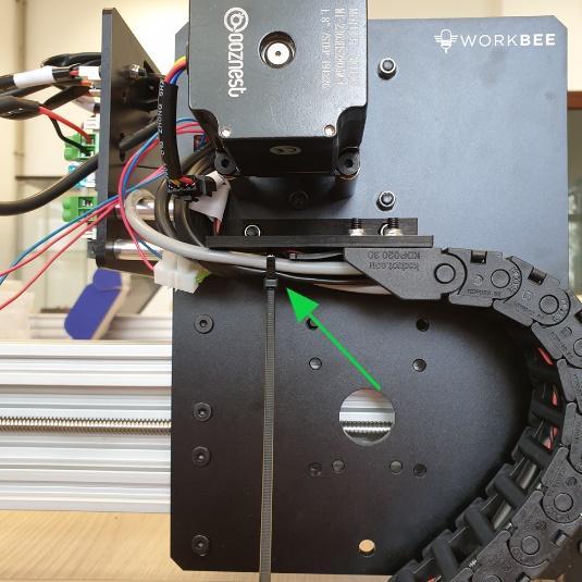
- Connect one end of the PLH3D-CNC Adapter-to-Laser Head Cable to the docking station on WorkBee mount. Attach the cable to the mount with a zip tie.
- More zip ties can be used to wrap the cable at the top of the Z-axis and on the other side of the X-axis.
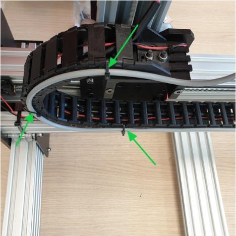
- Attach the cable to the X-axis drag chain or put it through it.
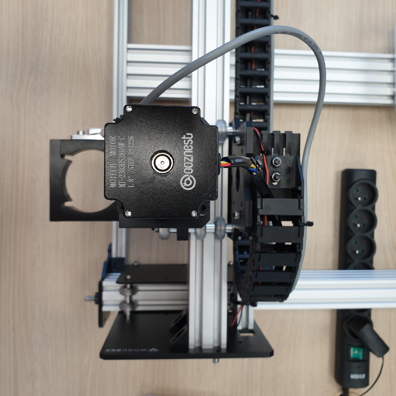
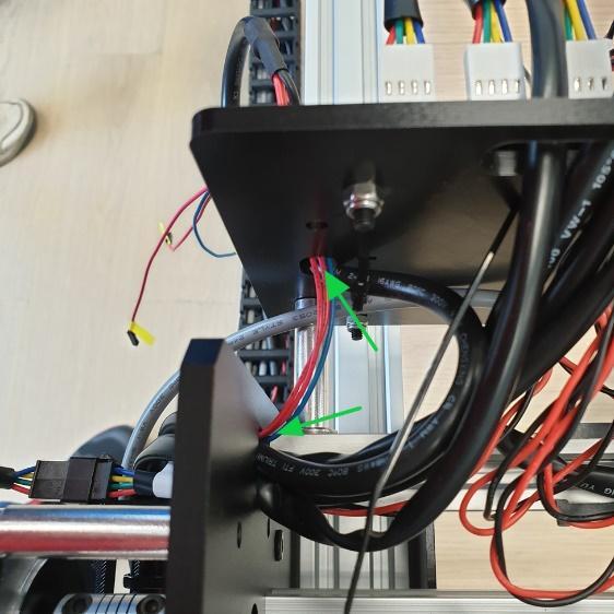
- Drag the cable behind the Duet mount.
- Put it under the X-axis motor and through the Y-axis drag chain.
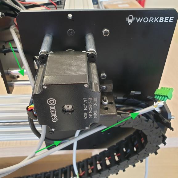
- Pull the cable from the other side of the Y-axis drag chain.

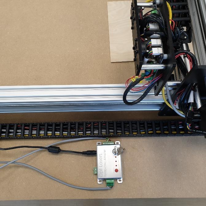
- Connect the cable to the output of the PLH3D-CNC Adapter.
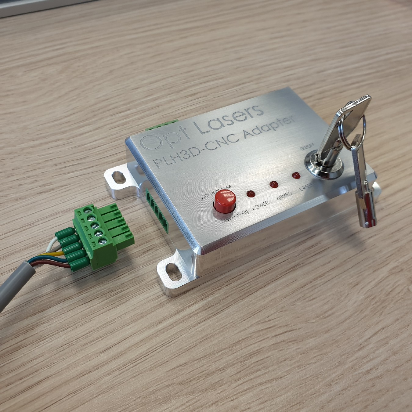
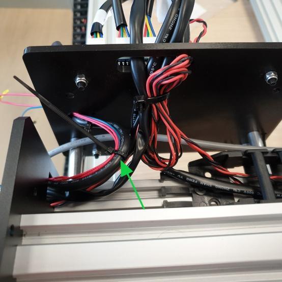
- Put the WorkBee Signal Cable into the Y-axis drag chain.
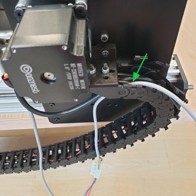
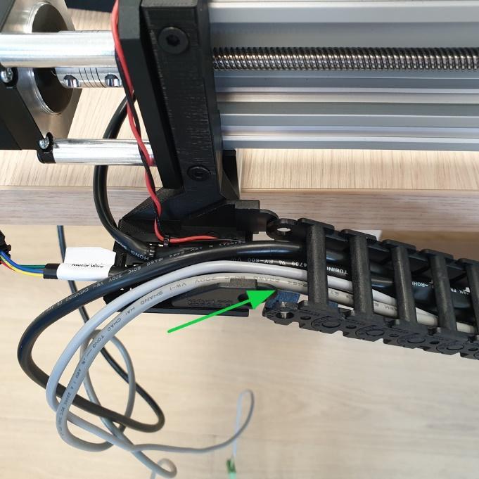
- Use a zip tie to attach the cable to the other wires.
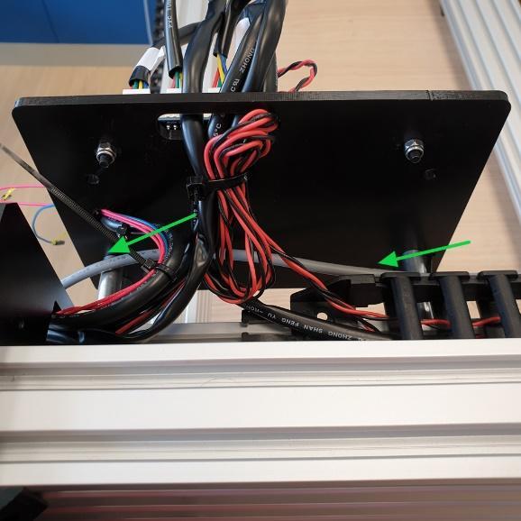
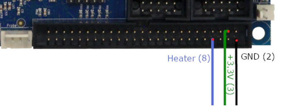
- Put the signal wires through the hole in the Y-plate (the one where the X-axis motor is mounted) and the hole in Duet mount.
- Secure the wires with a zip tie.
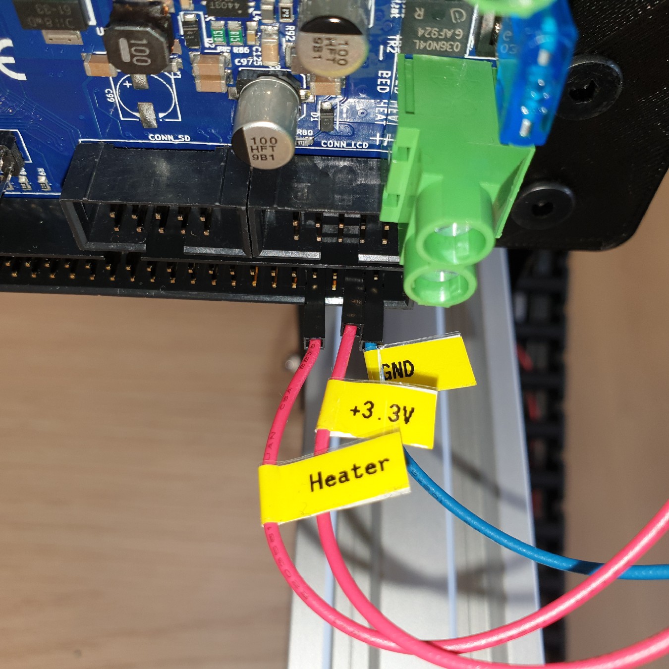
- Connect the wires to the Duet controller.
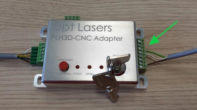
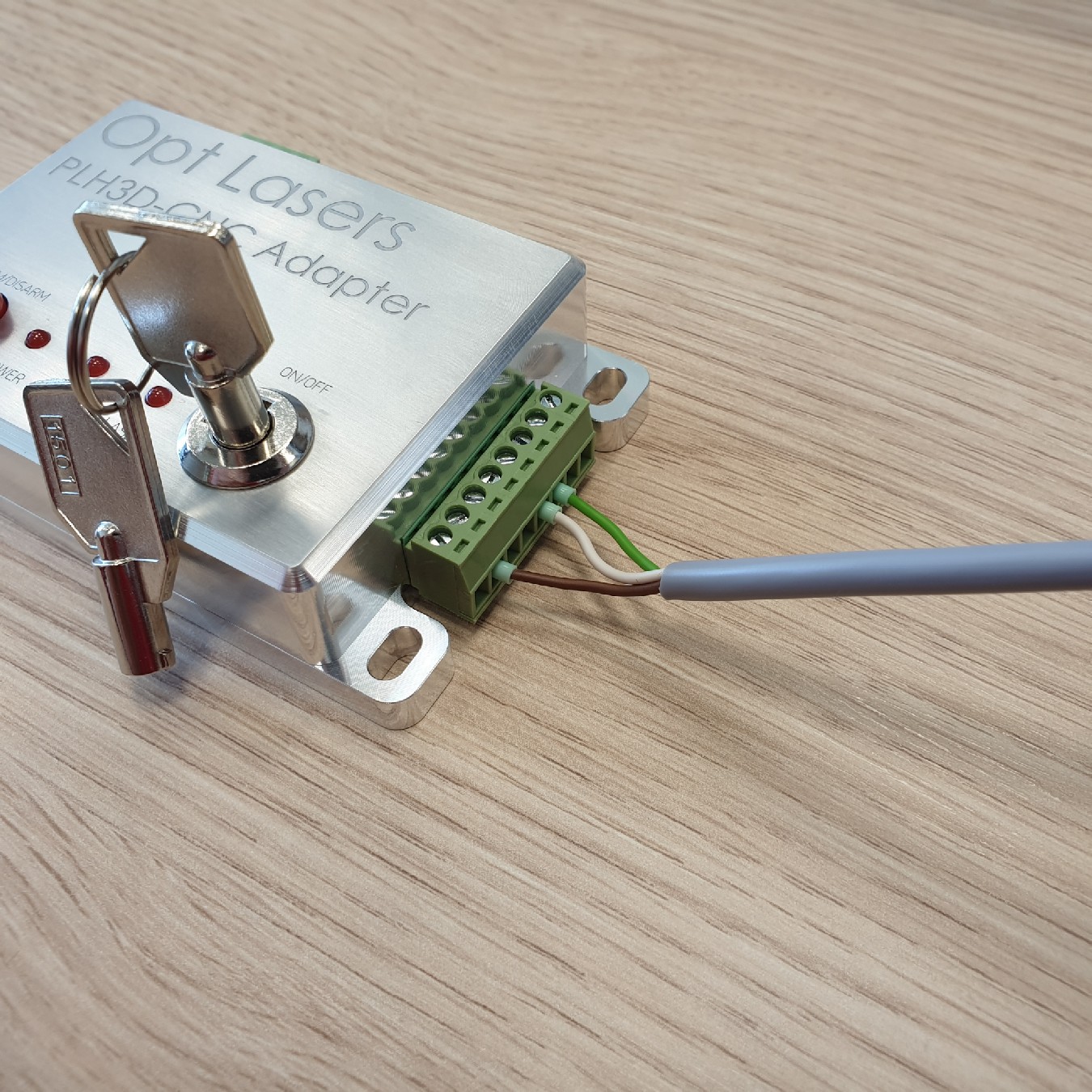
- Connect the WorkBee Signal Cable to the input of the PLH3D-CNC Adapter.
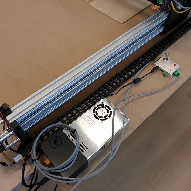
- Connect the 19V 2.5A Desktop Power Supply to the PLH3D-CNC Adapter.
|
|
|