I2R Laser Upgrade - About PLH3D-CNC Adapter
The PLH3D-CNC Adapter serves as a versatile interface and safety unit connected between a CNC machine and a high-performance PLH3D cutting laser head.
Many types of CNC machines (including 3D printers) available on the market, with different control voltage standards and levels available, may be used to control the PLH3D cutting and engraving laser. The PLH3D-CNC Adapter converts all these signals to the standard compatible with the PLH3D cutting laser.
The key function of the PLH3D-CNC Adapter is to “arm” and “disarm” the laser head. Arming means turning the head power supply on; the armed head is then able to generate a laser beam. Disarming (turning the head power supply off) brings the laser head to a safe state where generating a laser beam is completely impossible.
Key features of the PLH3D-CNC Adapter:
● Key-lock for preventing use by unauthorized personnel;
● Safe start;
● Mode button - can be used for arming/disarming, laser pulse test, and configuration enable settings;
● Status LEDs - power on, armed, laser working, and setting of Enable Modes;
● Connectors: PLH3D laser head, control, extensions, and external switches;
● Power connector;
● External desktop low-noise power supply;
● Machined aluminum quality enclosure;
● Optional PLH3D laser cables and signal cables dedicated to a CNC machine or controller type;
● Optional external key-lock, stop button, and sensors;
● Compatible with PLH3D laser heads;
● Can be configured for matching with the majority of CNC machines and 3D printers.
Built-in safety mechanisms prevent misuse and unexpected behavior in case of an emergency. The key switch protects the engraving and cutting laser head from being armed by children and unauthorized people. Arming the cutting laser head is always done manually by the user, by pressing a button. Special circuitry prevents arming during an internal electrical malfunction. The cutting laser head is automatically disarmed in case of an emergency: loss of the mains supply (grid power), PSU failure, breakage, or disconnection of the laser head cable. After disarming, the system remains in a safe state and rearming always requires the user to press the button.
Additional safety mechanisms can be incorporated into the system by adding up to two external switches (e.g. limit switch, key switch, or e-stop). There is also an additional extension connector for future needs.
Additional feature are industry-standard screw connectors. A dedicated, low-noise desktop power supply unit assures compatibility and reliability as well as eliminates problems caused by using third-party power supplies. The general status (power on, arming, laser working) may be inspected at a glance by looking at the three LEDs.
|
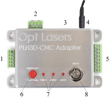
1 |
LASER HEAD TERMINAL BLOCK |
|
2 |
EXTERNAL SWITCH TERMINAL BLOCK |
|
3 |
EXTENSIONS CONNECTOR |
|
4 |
POWER SUPPLY CONNECTOR |
|
5 |
CONTROL TERMINAL BLOCK |
|
6 |
MODE BUTTON |
|
7 |
LED STATUS INDICATOR |
|
8 |
KEY SWITCH |
1. LASER HEAD TERMINAL BLOCK.
Attach the laser head cable here.
2. EXTERNAL SWITCH TERMINAL BLOCK
Up to two external switches (e.g. limit switch, key switch, e-stop) that arm/disarm the laser head can be connected to the PLH3D-CNC Adapter. When not using a switch, replace it with a jumper wire. Opening any external switch disarms the laser head immediately. Then, even if the switch has been closed again, the system will stay disarmed. The mode button must be pressed to rearm the laser head.
3. EXTENSIONS TERMINAL BLOCK Intended for future use.
4. POWER SUPPLY CONNECTOR
Plug in an external 15-24V DC power supply here. We strongly recommend using a dedicated power supply unit exclusively for the PLH3D-CNC Adapter.
5. CONTROL TERMINAL BLOCK
Controlling inputs and outputs are attached here.
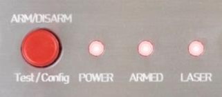
6. MODE BUTTON
a. Pressing the mode button once will arm the engraving and cutting laser head. Doing so will cause the ARMED LED indicator to light up showing the cutting laser head is in the armed state; the fan in the laser head starts to work as well. To disarm the laser head press and release the button again.
b. A test laser pulse can be generated in the armed state by pressing and holding the mode button for at least 1.5 seconds. An approximately one-second-long pulse at 100% power is then issued on the laser head control line. The LASER LED lights up confirming the appearance of the pulse. A single pulse will be generated even if the button is held for longer.
c. Holding the mode button while turning the power on activates the configuration mode where the “enable option” may be viewed and/or changed. Details can be found in the section For Advanced Users.
7. LED STATUS INDICATORS

- The POWER LED shows the presence of power and also signals supply errors.
- The ARMED LED shows the arming state and also signals both disarming by an external switch and disconnecting the cutting laser head.

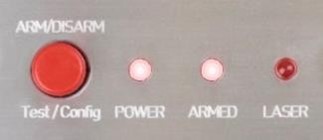
- The LASER LED shows the presence of the cutting laser head controlling signal (a steady one or a pulse-like). Note that controlling the cutting laser head is disabled in the disarmed state.
- In configuration mode, the LEDs show the current “enable option”. Refer to section For Advanced Users.
8. KEY SWITCH
Turn the key switch clockwise to the upper position to switch the PLH3D-CNC Adapter on. Turn the key switch counter-clockwise to the left position to switch the PLH3D-CNC Adapter off.
Further information can be found in Product User Manuals/PLH3D-CNC Adapter - User Manuals