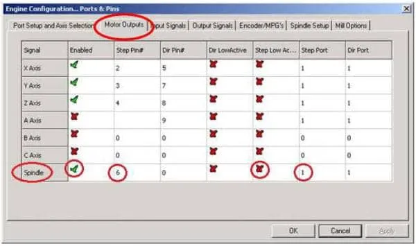
1. Engine Configuration… Ports & Pins - Motor Outputs
2. Engine Configuration… Ports & Pins - Spindle Setup
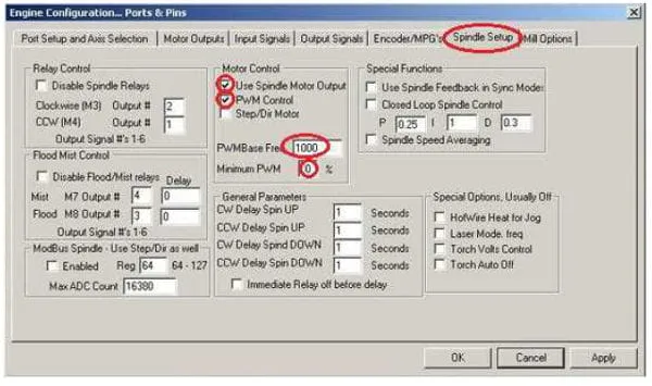
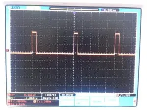
IMPORTANT! You need to set PWM Base Freq between 5 000 and 10 000 Hz. Setting lower frequency value (e.g. 1000 Hz, 10% duty) is incorrect because laser is turned on at maximum power only by 0.1 milliseconds and turned off by 0.9 milliseconds. As a result, the power of the laser isn’t averaged and cutting (engraving) line is dotted with long pauses especially if engraving speed is high.
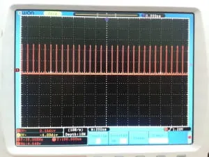
If you set higher base frequency, for example, 10 000 Hz and the same duty, a laser is turned on at maximum power 10 times per 1 millisecond. As a result, the power of the laser is averaged and cutting (engraving) line is homogenous.
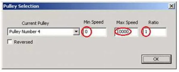
3. Pulley Selection
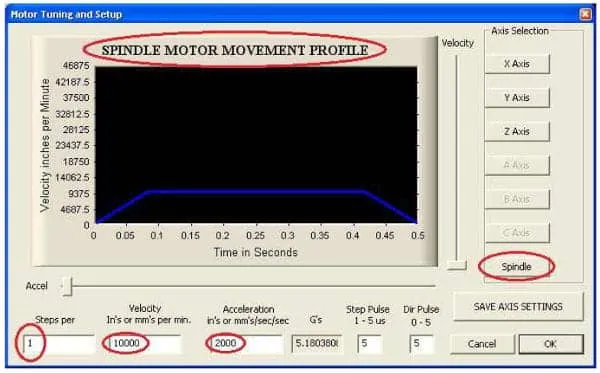
4. Motor Tuning and Setup
You can connect pin number 6 of the breakout board (or another, if you set them) directly to the TTL input of the laser head. After these, you can enter a spindle speed between 500 and 10,000 and Mach will control the laser as a spindle. The spindle speed will adjust the laser power.
