Personalizing an item by cutting or engraving is one of the most effective ways to make it unique. Whether it’s for personal uses, to serve as a gift, or a commercial product for your customer, it is crucial to get the perfect shape and shade. In order to achieve that, an accurate focusing is required for the proper operation of your CNC machine.
In this guide, you will learn how to calibrate the working distance of your machine. All brand new PLH3D series laser heads have their focus set to 60 mm. This focal distance provides a well-optimized beam waist that administers sufficient power density for a great deal of cutting and engraving applications. While it is recommended to start off with a factory-set focal spot, you can alter the focus spot distance from the face of the laser head by rotating the lens clockwise, or counterclockwise. In general:
-
A shorter working distance for a given lens generates a smaller beam waist, hence higher power density. This is often used for higher speed engraving, higher resolution engraving, or in the case of processing materials that require higher power density. It is important to note that this results in a faster convergence and divergence around the beam waist, which may have adverse effects, for example, when a thicker material is cut.
-
A longer working distance for a given lens generates a larger beam waist, hence lower power density. It may be preferred for cutting thicker materials (since the divergence and convergence around the beam waist is reduced), engraving a wider line, or when a substantial distance between the laser head and the plane of the specimen to be processed is required.
Note: If you choose to move the mounted lens, it is imperative to verify that it is secured adequately deep inside the laser head so that it doesn’t change its position before powering on the system.
-
First Calibration Run
-
Put the safety glasses on.
-
Please mount and connect the laser head on your CNC machine.
-
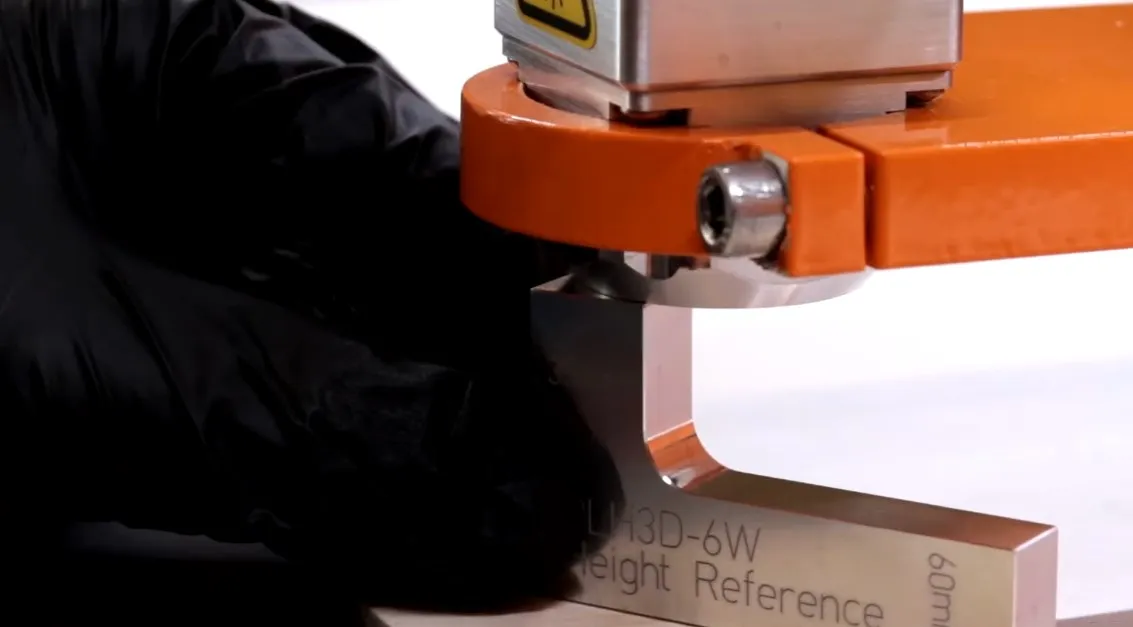
Next, use the height reference tool (or another distance measuring tool of choice) to find the proper distance on the z-axis. The tool can set the distance to 35 mm or 60 mm.
-
Position the laser head 60 mm from the front of the laser head or 35 mm from the nozzle to the workpiece. The picture below shows the correct positioning with the nozzle equipped:
-
Please zero the z-position of the machine using your software.
-
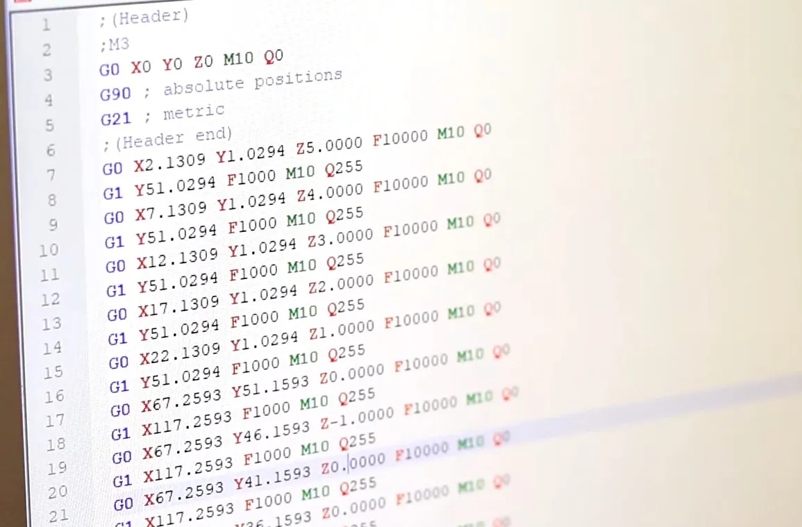
For the next step, create a file with 11 vertical and 11 horizontal lines and generate the corresponding G-code. Since the G-Code was generated assuming the same height for all the lines, the z value should be manually altered for each line of the G-code, as depicted in a picture below. Once created, this file can be reused multiple times to quickly calibrate the working distance.
-
Please refer to https://optlasersgrav.com/material-laser-cutting-tests# for the choice of an initial feed rate. Suggested feed rates are shown in the second section, namely “Engraving Speed Comparison”. A feed rate of 16 mm/s was used for plywood in the example depicted on the next page..
-
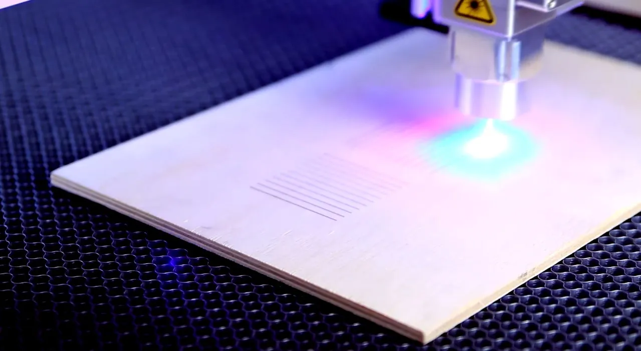
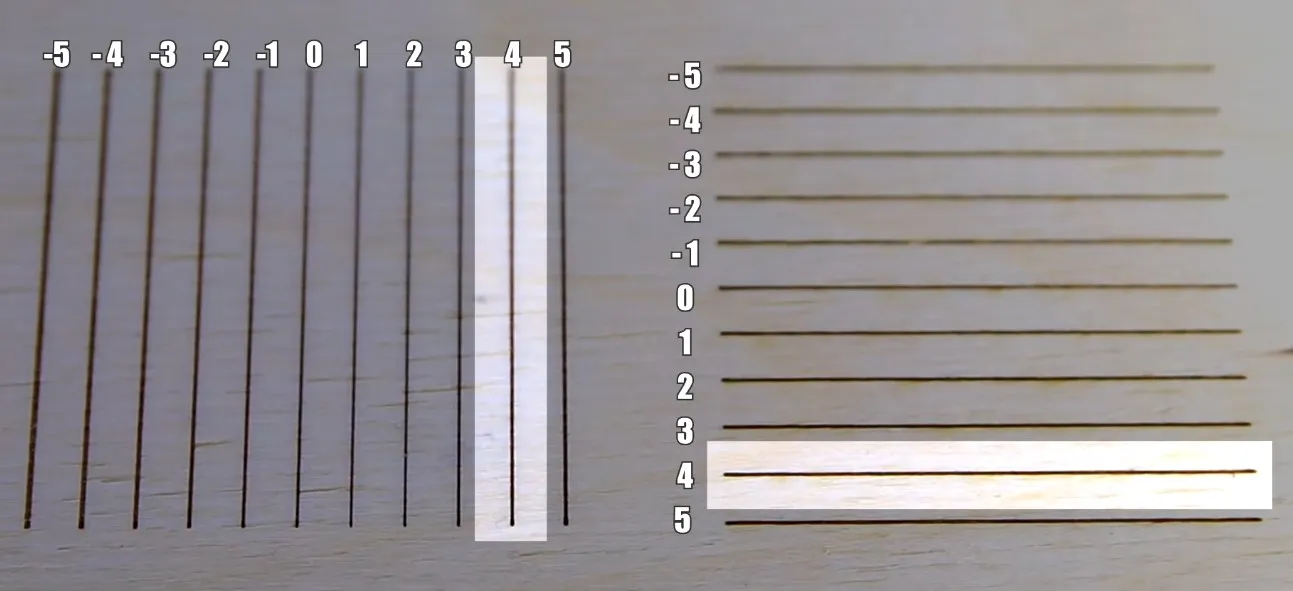
Engrave the aforementioned two sets of lines. The picture below shows two sets of 11 lines being engraved from -5mm, through 0 mm, up to +5 mm.
-
Working out the proper working distance for cutting
-
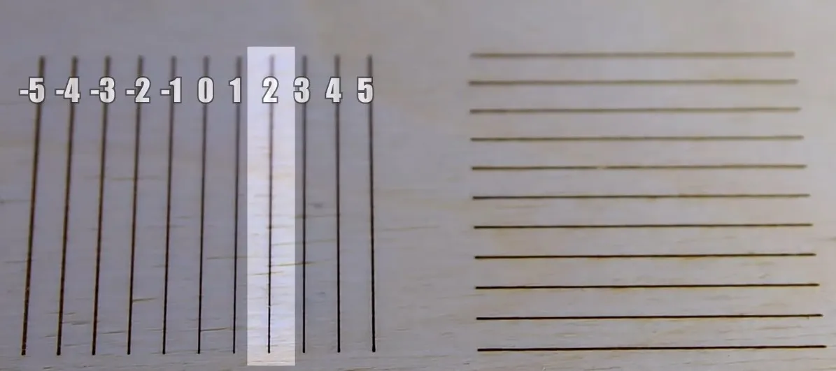
Look at the engraved lines. Choose the single thinnest line from both sets of lines, then use it to make the z-axis correction. In the photo below the line marked as “2” appears to be the thinnest line. This line corresponds to +2 mm versus the z-axis’ zero position. As it is not always easy to tell which line is the thinnest, it is recommended to use a magnifying glass, or a microscope. You can also use an app on your phone, for example Magnifying Glass & Microscope from Hantor on Google Play Store.
-
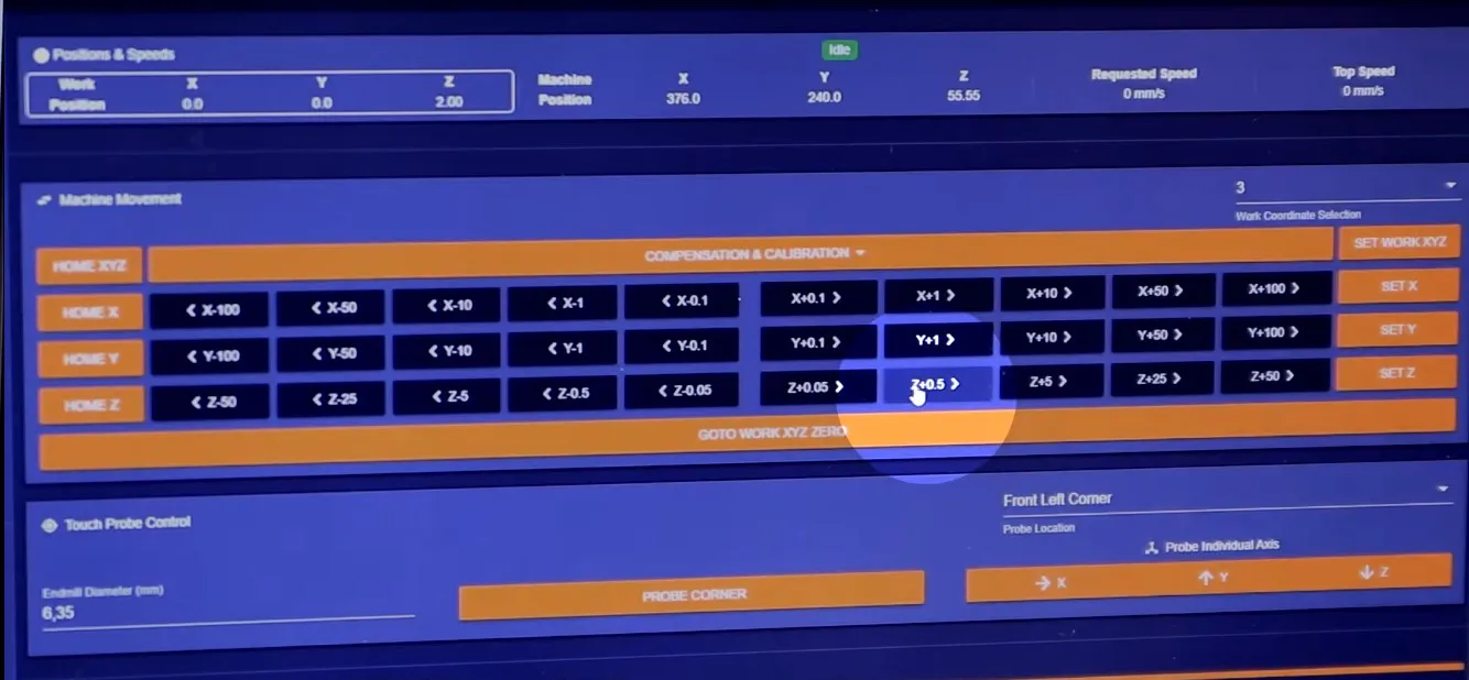
Once the thinnest line has been identified, please apply the correction to the z-axis (change the actual z position of the router by adding or subtracting enough length in increments), as shown below:
-
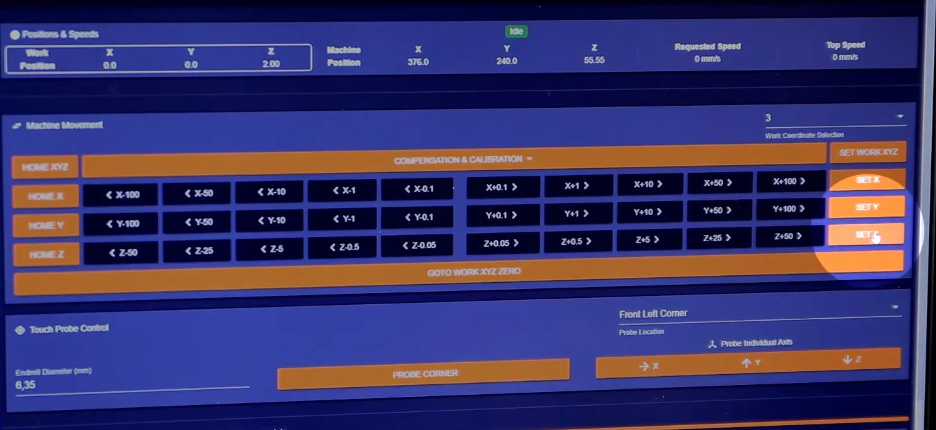
Now please zero your z-axis position by clicking the “SET Z” button, just like in the photo below:
-
If a higher precision is desirable, you can prepare a similar G-code for the -1 mm to +1 mm range. In this case you can choose to increment by 0.2 mm. Engrave another two sets of lines. Afterwards, please choose the thinnest line again. Then apply the correction to the z-axis again by clicking the “SET Z” button and zero the z-axis.
-
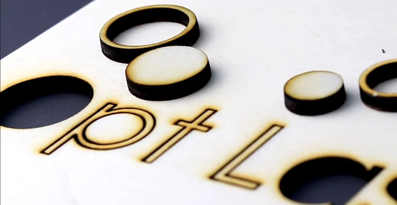
After correction, you can engrave a simple pattern to check if the setting is correct.
-
The beam spot now has a rectangular shape after the operating distance has been adjusted and should be equal to 250 um by 5um. This shape brings about the highest power density of the beam, which in turn makes it possible to reach the highest cutting speeds. The smallest beam spot possible is preferred for cutting applications due to higher power density.
-
A sample cutting test:
-
Please continue from point 4.1.
-
Working out the proper working distance for engraving
-
For engraving, especially on soft materials, a square beam spot shape is preferred. In order to achieve that, please choose lines with the same thickness from both sets of lines and make the z-axis correction. In the example below, the lines with +4 mm versus the z-axis’ zero position seem to be the ones with the same thickness.
-
Now, please adjust your router’s z position in increments so that it is equal to the position of the lines with the same thickness from the previous point (“+4” mm in the example above). Next, please zero your z-axis position by clicking the “SET Z” button. Finally, you can engrave a simple pattern to test the settings.
-
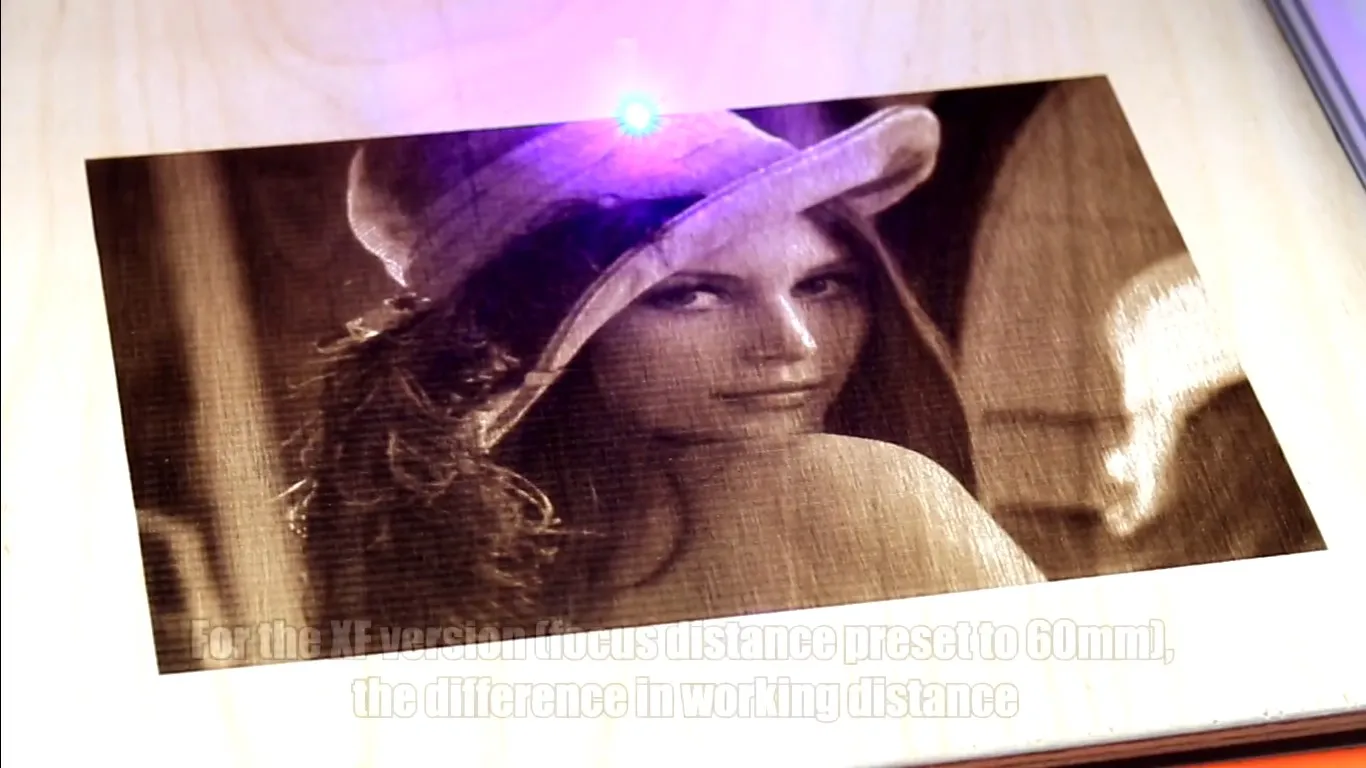
For the XF version (and the focus distance preset to 60 mm), the difference in working distance between the square spot and the smallest possible spot is around 4.4 mm, while for uSpot it’s around 1.8 mm.
-
For picture engraving, a square beam spot is the best option, but some materials (such as stainless steel or stone) may require higher power density to be processed. For optimal cutting performance a smaller beam spot is usually preferred.
-
Please continue from point 4.1.
-
Working out the perfect feed rate
-
Open the file from point 1.6. This time, please change all the z-axis distances to 0 and modify the feed rate for each line instead. You can use, for example, 50 mm/s or 100 mm/s increments.
-
Engrave a set of lines.
-
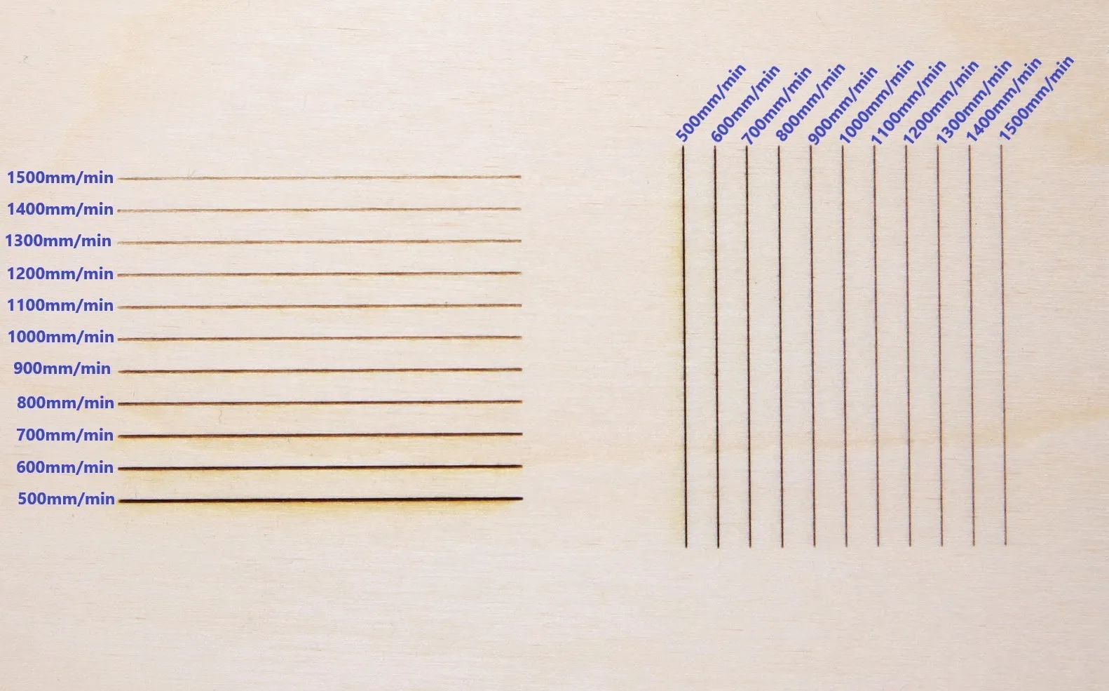
In general, the faster the feed rate, the less the material burns. On the other hand, if the feed rate is too high, the line might either start to wiggle throughout its length or stop cutting the specimen in a single pass due to not having sufficient power density. The picture below shows the feed rate calibration for wood, running from 500 mm/s to 1500 mm/s with 100 mm/s increments:
-
Choose the line with the feed rate that suits your needs.
-
Apply the correction of the feed rate on your CNC software application.
Have fun with our products!
For any questions, please contact us via: