Mach3 Configuration - Avid CNC Laser Upgrade
Important: Please make sure that you have the ESS plugin for Mach 3
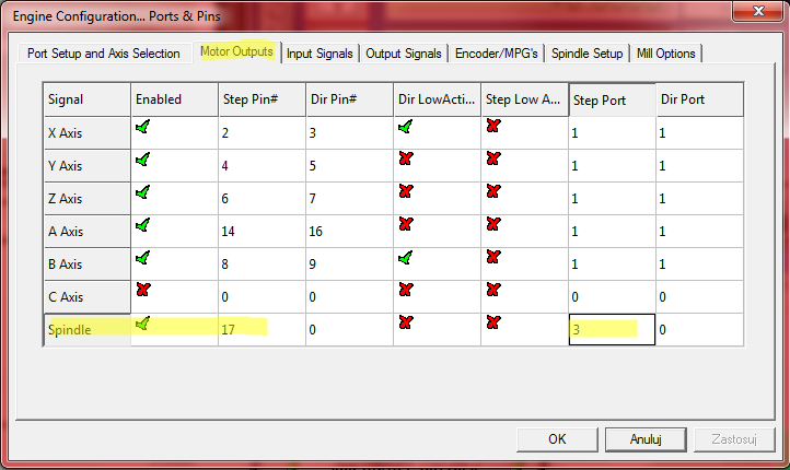
Connect Spindle PWM signal to Pin 17 Port 3 in Mach3’s Menu -> Config -> Port and Pins -> Motor Outputs
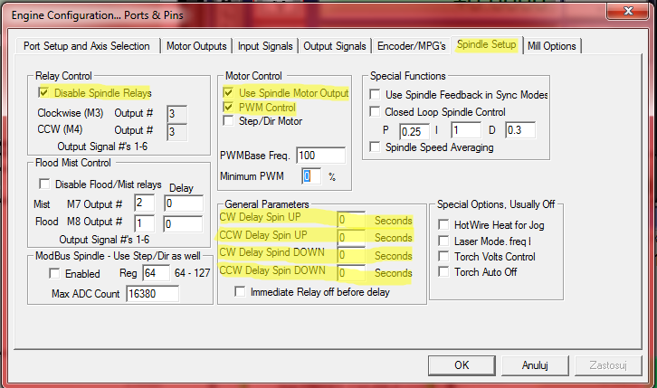
In Mach3's Menu -> Config -> Ports & Pins -> Spindle Setup: disable Spindle Relays, set all delays to 0, enable PWM control and use Spindle Motor Output:
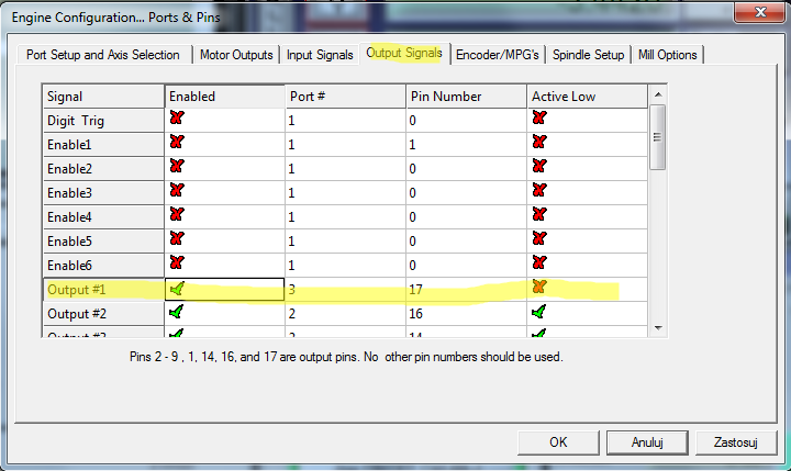
Set output signal in Mach3's Menu -> Config -> Ports & Pins -> Output Signals to port 3 pin 17
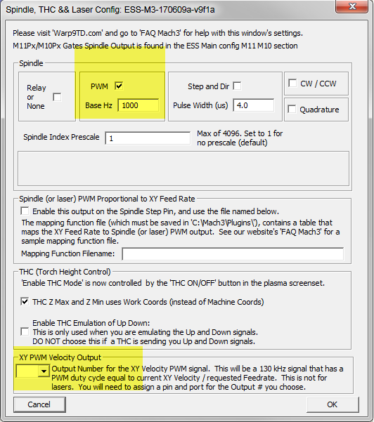
In Mach3's Menu ->Plugin Control -> Spindle, THC & Laser Config
- Please make sure that the XY PWM velocity output is left blank
- Please make sure that the PWM is ticked. You should also change the base Hz setting to 10 000 Hz (ie. different than below)
- You can also verify that the pulse width is the same as below, ie 4 µs:
- The Spindle (or laser) PWM Proportional to XY Feed Rate should be left blank:
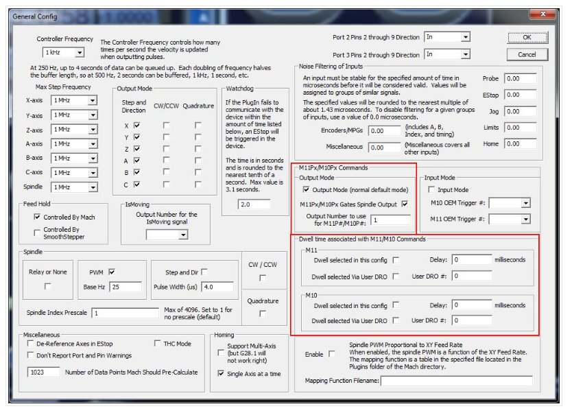
In Mach3's Menu ->Plugin Control -> Main Config associate M11Px/M10Px commands with Output #1 that you set in paragraph 4. It is important to place a check next to M11Px/M10Px Gates Spindle Output.
Please note that in the third picture on this page, the PWM pin is set as Output #1. This directly corresponds to the M11Px and M10Px commands -> by putting 1 as the output number in the window below (Plugin Control/ Main Config), it makes your output pin (pin 17 on Port 3) react to M11P1 (turn on the laser) and M10P1 commands (turn off the laser).
This section can alternatively be here. If you have it here please make sure that the dwell times are set to 0 and all boxes in the dwell section do not have a check next to them:
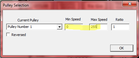
In Mach3's Menu -> Config -> Pulley Selection choose the pulley that you will be using and set Min and Max Speed parameters which corresponds to accordingly: 0% and 100% of PWM duty cycle. Set them to 0 and 255.
To cut or engrave, it is necessary to generate the appropriate G-code that using the following commands:
|
M11P1 |
Laser ON |
|
M10P1 |
Laser OFF |
|
SXXX |
PWM duty where XXX is number between 0 and 255 (e.g.: 0 = 0% and 255 = 100%) |
Connect green connector of the adapter to the laser head and connect the power supply.
If there are any further questions or if anything is not clear, please contact us at https://optlasers.com/contact-us
You should also join our supportive Opt Lasers Grav community: